A while ago I purchased an electrical standing desk from Flexispot.de. During assembly I found out that the display controls are connected via a RJ45 cable to the motor control box, and that the motor control box even has a second RJ45 input.
Challenge accepted! How cool would it be if I can control my desk by voice or if I can pull statistics to understand if I stand too less. (like with my manual IKEA desk that I have used twice in four years…)
The first step was to open the controller and to look at the board. So nice of LoctekMotion (the manufacturer) that they wrote down the pin output description on the board, saves me a lot of time. Now the fun starts.
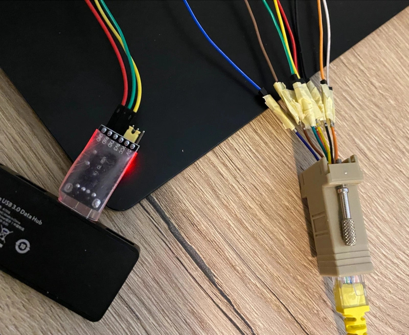
I am more comfortable writing software than tinkering with electronics and cables. From the start I got help from the Dutch tweakers.net community, where they guided me through the process. I started by using a RJ45 to RS232) together with dupont cables to attach it to a CP2102 controller. This made it easy to start tinkering with it, without cutting cables or soldering.
Now I am able to read the incoming bits via RealTherm, thus it shows that my RX/TX are working.
Eventually I found out that many people already did research the same issues, which made figuring out the commands a lot easier! Since I am more fluent in Python than in C++ / Arduino, I started with a Raspberry Pi. This did allow me to quickly prototype and test all the features.
When I got this working, I moved over to ESPHome. This worked like a charm, after I figured out my RX and TX were reversed… The last part was to write a piece of custom code to decode the 7 digit segment output that is sent to the display.
Eventually this results in the following; where I am able to move the desk up and down (cover entity) and where I can set it to one of the four presets (switch entity). After a command has been executed it will pull the new height and show it on a sensor entity.
Other control panels should be supported if they are from LoctekMotion. I have had some other users reach out to me on GitHub with other control panels, thus I hope to add them to the README eventually.
I have the HS11A-1 which has the same exact button configuration as the HS01B-1… I haven’t had a chance to crack it open yet to check the pinout though.
So @imick - I recently purchased a standing desk from Office Depot, and it has the HS13A-1 controller and dual RJ-45 ports. If I wanted to set your project up, what would I need to purchase aside from an ESP8266? I’m a complete novice to ESP32, but I’ve been meaning to give it a go.
Any videos you could recommend on how to get started?
I’ve watched a few videos and I’ve purchased an ESP32 which should arrive tomorrow.
I noticed that your instructions look like they’re for the ESP8266 which from the videos I watched is the predecessor to the ESP32?
With ESP Home and Home Assistant, I think I can get the board online, connected and running. I’m just not sure how to attach the RJ-45 to the board itself.
In your post above you used what looks like an RJ-45 Serial connector? On your github it looks like you connected the wires in the ethernet cables to the pins on the board itself? Should I be grabbing something like this to connect one end to the pin on the board, and then the other end twist it with the ethernet cable / electrical tape?
I think I’m most of the way there, just a little lost on how to connect the ESP32 to the wires. I’ve terminated ethernet cables before, so I should be good there. I can follow the pattern you set forth in the documentation for that.
Hi @stratotally, happy to help. Feel free to contact me on Discord (iMick#1903) as well. You can indeed also use an ESP32, just change the board in your ESPHome config.
There are multiple options to get this working. In my end solution I just used an ethernet cable which I cut, and I added dupont connectors to the end on one side. But during testing I used a RJ45 to RS232 adapter, which I connected to the dupont cables. This made testing convenient in the beginning.
So I think I’m almost there. GND = Ground, which makes sense because the control panel is powered by the RJ-45 cable from the controller. Would I take that to mean that the ESP32 could also be powered by the cables? (Update: Looks like thats a yes, read below!)
I’ve purchased some dupont connectors and I’m just waiting for them to arrive. Meanwhile I’m trying to match up your photo with the pinouts, and compare that to your documentation on github. Thinking through this aloud, if I take your mapping here:
The “original cable” is the cable that came with the desk, right? And you’re providing a mapping to a normal ethernet configuration in the last column.
So I should take this mapping, and compare it to the ESPHome mapping?
I see you have indicators like “D6” and “D5” in the first column. So I just need to match those up with the ESP32 pinouts, right? And since the ESP32 supports a 5V, that means I can power it from the desk itself?
I spoke with imick and the ethernet cable color column was added by a contributor. I think that the “original cable color” were the colors that were with imick’s cable, and what they corresponded to in the pins at the connector. Since the last column (T568B) follows the standard, I think thats what I’m going to use. As long as I line them up with the “Name” column to the cable color in the last column, and then match that with the second screenshot on the pinouts, I should be good.
However, ESP32 has different pinouts than ESP8266. I’ve been researching this and trying to take a crash course in arduino, and I think I might be close? I’m still waiting for my duponts to arrive to confirm it. From my research, I ESP8266 uses certain pins for certain functions. The four we need are:
GND - Ground
D5 - GPIO14 / SCLK (Slave Clock - but we have this mapped to TX for transmit.
D6 - GPIO12 - MISO (Master in, slave out - which I read as communication from the slave device to the ESP, we have this mapped to RX for Receive, so I think we’re good here.)
D2 - GPIO4 - SDA (Serial Data Pin, where communication is sent back and forth between the devices)
From my research, you can set (certain) GPIO pins to be whatever you want. I think I need to add the following to my yaml file for ESPHome to match the original ESP8226 config?
To be honest, I am not sure what i2c is and what you need to do? It should be as simple as just changing the tx and rx pins to the one that you did choose, and connecting the ground.
I’ve crimped, and then re-crimped. Still couldn’t seem to make this work. I also removed the i2c and spi sections, since it sounds like I just need to identify which pin to work with. Still no dice.
I think what the contributor was trying to do with adding in the RJ-45 colors to the table in the last column was identify which wires in a typical RJ-45 correspond to which wire in the cable/display that comes with the desk. However, I’ve just realized that they have it backwards.
Your original column with the colors Brown, White, Purple, etc. If I look at the RJ-45 end of the cable that comes with the desk, I see these colors. There isn’t a “purple” in typical ethernet wires, so they were trying to match what it’d be in a typical cable.
However, in your photo here:
…it looks like you’re using brown/white for your D2 pin? Then I compared the pin numbers to this diagram:
…and bam. The contributor listed the colors backwards! This would explain your photo…and why my setup isn’t working. Sigh. Time to do some more crimping and hopefully I’ll be submitting a correction to your repo README as soon as I get mine working.
Never mind. While the pin numbers were backwards compared to the diagram I found, the cross map looks like it is correct.
@imick Would you be able to take a closer pic of your board and/or list which ethernet wire colors are going to each pinout? Is that the white-brown that you’re using?
unfortunately i only have a flexispot with a basic keypad that only does up and down and has no RJ45 port. has anybody ever looked into making one of those smart?
could be a matter of just closing certain circuits depending on which direction you want to go?