Wiegand protocol RFID readers known to work with ESPHome?

You can either:
a) download the code from Github (linked above) and place it on your HA server in the directory homeassistant/esphome/custom_components, then use it in your YAML
b) Use the Github link in your YAML to download the code every time you rebuild your ESPHome device.

Samuel has provided examples on his Github page of everything.

sorry newbie) Show code for example)

  1. Go to SSieb’s github link.
  2. Click down to the directory ssieb/custom_components/wiegand/
  3. Ignore the file README.md - that’s the web page text you’re seeing beneath the files list - it doesn’t compile
  4. Click on each of these three file links:

and save the files to your local PC/desktop/laptop/Mac/whatever. Then upload the files (if you’re on Windows, WinSCP is great for this) to your Home Assistant system, in the path /???/???/homeassistant/esphome/custom_components/wiegand/

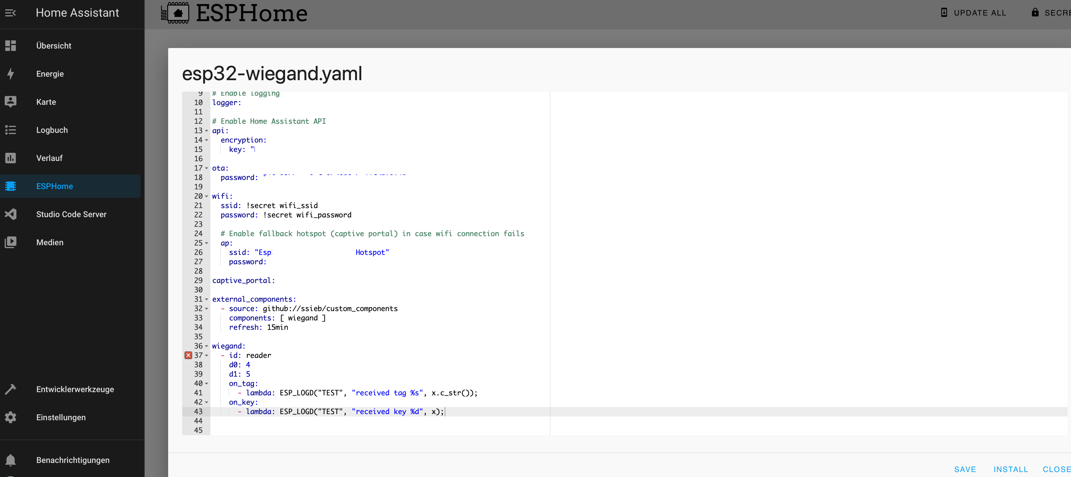
Once the python, .h, and .cpp file are present on the Home Assistant system, edit your ESPHome device YAML file like so:

wiegand:
  - id: reader
    d0: 4
    d1: 5
    on_tag:
      - lambda: ESP_LOGD("TEST", "received tag %s", x.c_str());

id is your ESPHome device name/id
d0: 4 indicates you’re using Pin 4 on your ESP for the Data0 line from the Wiegand reader (Green wire)
d1: 5 indicates you’re using Pin 5 on your ESP for the Data1 line from the Wiegand reader (White wire)

Don’t forget to connect your GND/COM black wire from the Wiegand device to the ESP8266 or ESP32 device, or your signals will never be seen. :wink:

On my Ai-Thinker clone ESP32-CAM, when adding the Wiegand custom component, the camera fails to initialize. I’ve designated GPIO 12 and GPIO 13 for the Wiegand data lines. I chose these because they are exposed on the ESP32-Cam device, and only used for the SD card, which isn’t used by ESPHome.

[15:36:01][I][logger:214]: Log initialized
[15:36:01][C][ota:461]: There have been 0 suspected unsuccessful boot attempts.
[15:36:01][D][esp32.preferences:114]: Saving preferences to flash...
[15:36:01][I][app:029]: Running through setup()...
[15:36:02][E][camera.c:1327] camera_init(): gpio_install_isr_service failed (105)
[15:36:02][E][camera.c:1406] esp_camera_init(): Camera init failed with error 0x105
[15:36:02][E][esp32_camera:024]: esp_camera_init failed: ESP_ERR_NOT_FOUND
[15:36:02][E][component:112]: Component esp32_camera was marked as failed.

Here’s the YAML output:

[15:36:06][C][logger:233]: Logger:
[15:36:06][C][logger:234]:   Level: DEBUG
[15:36:06][C][logger:235]:   Log Baud Rate: 115200
[15:36:06][C][logger:236]:   Hardware UART: UART0
[15:36:06][C][wiegand.text_sensor:059]: Wiegand reader:
[15:36:06][C][wiegand.text_sensor:060]:   D0 pin: GPIO12
[15:36:06][C][wiegand.text_sensor:061]:   D1 pin: GPIO13
[15:36:06][C][esp32_camera:048]: ESP32 Camera:
[15:36:06][C][esp32_camera:049]:   Name: esp32cam
[15:36:06][C][esp32_camera:050]:   Internal: NO
[15:36:06][C][esp32_camera:052]:   Data Pins: D0:5 D1:18 D2:19 D3:21 D4:36 D5:39 D6:34 D7:35
[15:36:06][C][esp32_camera:053]:   VSYNC Pin: 25
[15:36:06][C][esp32_camera:054]:   HREF Pin: 23
[15:36:06][C][esp32_camera:055]:   Pixel Clock Pin: 22
[15:36:06][C][esp32_camera:056]:   External Clock: Pin:0 Frequency:20000000
[15:36:06][C][esp32_camera:057]:   I2C Pins: SDA:26 SCL:27
[15:36:06][C][esp32_camera:058]:   Reset Pin: -1
[15:36:06][C][esp32_camera:088]:   Resolution: 1600x1200 (UXGA)
[15:36:06][E][esp32_camera:095]:   Setup Failed: ESP_ERR_NOT_FOUND
[15:36:06][C][psram:020]: PSRAM:
[15:36:06][C][psram:021]:   Available: YES

and the actual ESPHome YAML code:

esphome:
  name: esp32cam-wiegand
    
esp32:
  board: esp32dev
  framework:
    type: arduino
    version: recommended

# Enable logging
logger:

# Enable Home Assistant API
api:

ota:
  password: **redacted**

wifi:
  ssid: IOT
  password: **redacted**

# Example configuration entry
esp32_camera:
  name: esp32cam
  external_clock:
    pin: GPIO0
    frequency: 20MHz
  i2c_pins:
    sda: GPIO26
    scl: GPIO27
  data_pins: [GPIO5, GPIO18, GPIO19, GPIO21, GPIO36, GPIO39, GPIO34, GPIO35]
  vsync_pin: GPIO25
  href_pin: GPIO23
  pixel_clock_pin: GPIO22
  power_down_pin: GPIO32
  resolution: UXGA
  
wiegand:
  - id: reader
    d0: 12
    d1: 13
    on_tag:
      - lambda: ESP_LOGD("TEST", "received tag %s", x.c_str());
2 Likes

thank you very much!!!

The good news is, this custom component by ssieb is working well with my Retekess keypad/tag reader on the ESP32-CAM device. It just wasn’t initializing the camera properly. I’ve switched from IO12 and IO13 to IO14 and IO15, but it still fails to init the camera device. I suspect it may be a power supply issue, where my USB port isn’t providing enough power for the ESP32CAM to initialize properly.

ESPHome complained about strapping pins if I used either IO12 or IO15 so I switched to IO13 and IO14. Camera still does not initialize properly, even at 800x600 resolution, with the 5V 3A power supply. :frowning: :frowning:

I also tried removing the HOT keyword from the two Wiegand interrupt service routines (ISRs) but it did not help. It does still read tags correctly without this HOT keyword. I’ll definitely put it back, as if @ssieb wrote it that way, I trust it is correct.

1 Like

or instead of doing steps 1 to uhh… saving files, uploading etc, just paste this in your config:

external_components:
  - source: github://ssieb/custom_components
    components: [ wiegand ]
    refresh: 15min
2 Likes

Next steps: Discussing with ssieb and possibly Otto Winter any possible causes for incompatibility between ESP32CAM OV2640 camera code and the (very function yet still minimal) Wiegand code from ssieb.

These discussions take place on the ESPHome Discord, if anyone is ever interested.

I’ve just reviewed the source code for the ESP32 camera in ESPHome, and at first glance there does not appear to be any reason whatsoever for any incompatibility between it and Wiegand protocol handling. Wiegand uses two data pins and ISRs, camera uses many I2C data pins and no ISRs except for any possibly built into low-level I2C communication. /me scratches head . . :upside_down_face:

In the file esp32_camera.cpp, the camera’s setup priority is established:

float ESP32Camera::get_setup_priority() const { return setup_priority::DATA; }

I believe if we initialize the Wiegand component AFTER the camera, it may work properly. Will try to find out today… The next step after DATA is PROCESSOR.

2 Likes

Unfortunately, I have some BAD NEWS for everyone reading and interested. :frowning:

The ESP32-Cam modules and low-level initialization code for the camera inject their own ‘special’ interrupt handling on the ESP32 processor, which prevents ESPHome’s (Arduino) interrupts from processing properly. :frowning: I’ve included a link below describing the source of the error 105 that is occurring on the ESP32Cam board whenever the Wiegand code is loaded. @ssieb commented below. I bolded one part of his comments.

ESP32 CAM: gpio_install_isr_service failed (105) - ESP32 Forum
seems there are ISRs in the ESP32 camera_init routine (where this error 105 is occurring) that may be the source of the issue.

## ssieb Today at 2:33 PM
Ah, that’s terrible. Looks like they won’t be compatible…

The espcam is incompatible with any normal interrupt use. You would probably have the same problem if you used a rotary encoder for example.

1 Like

Hi everyone
Just getting ready to play with Wiegand. How do you use the component to get the keypad code? Unit I am getting has the card and code

Hi Fred,
i am not able to install the firmware.
Always same error : “Component not found: wiegand.”
My ESP`s. All working well :


My .yaml :

custom_components folder with wiegand files:

Error Message !:

Guten abend, @kepir !! :slight_smile:

Follow @nejccc example a few posts above, using the github link.

Hallo @FredTheFrog ,
auch dir einen wunderschönen guten Abend…

I tried it before. Same problem. :


I’ve updated the component with keypad support. You need to import more components now. See the README.

1 Like

Update :
some custom components are working without an error and some do not.
Here is an example for a working one.


Is there anybody can help me ?

You picked the one that literally crashes the device as the working one? :rofl:
But why are you asking about this here? The topic is Wiegand readers. If that component isn’t working, then it might be relevant to ask here. But if other components aren’t working, then you should file an issue on the repo or come find me on the esphome Discord server.

Hi, I’m building a new house and excited at the idea of integrating this, using it to trigger an electric door strike.

I haven’t gone through the project in detail, but I’m at the point of pre-wiring the house now. What do I need to plan for? Just 12v power beside the door frame?

I’m not to familiar with ESPHome, is there any reasonable way to adapt this to a fully wired solution? I’d prefer to not lose access if my wifi network goes down. I noticed this, does it mean I can do wired eithernet with ESP32? Would it conflict with this project?

Thanks!

David

devices will work without internet. any device on esphome can be standalone and work.

and yes you need 12v only you need to understand that the esp and components work from 5v. they need a step down converter. I made such a project at work but on a simple rfid reader

devices will work without internet. any device on esphome can be standalone and work.

Ok but what about other failure modes? If the link to homesassistant is down, or homeassistant itself is down, I’d still like my door access to function. I guess that would mean this device needs to keep a cache of authorized hashes and also be able to directly switch the relay connected to the door strike. I don’t think this project does that already but might be a cool extension.

Most Wiegand tag readers include several wires in the bundle, where some connect to the ESP microprocessor (green and white, the two DATA lines), others connect to the 5VDC power supply (Vin/red and GND/black), while two others serve to change the color of the LED on the reader or to beep the beeper/buzzer on the reader. These two lines typically react when connected to the GND ground connection point, FYI.

Using a combination two-relay or four-relay board with embedded ESP microprocessor, you can save some wiring effort. These boards are typically used for sprinkler controllers or lighting controllers, or even gate/latch/hasp controllers. If you hard-code a list of two or three or four tag IDs in your ESPHome YAML, then your device can function to open/unlock/lock even if the LAN or Home Assistant server is down or offline.