Hello everyone,
I’ve ordered on Banggood an Arilux AL-LC03 but the chip inside is not a 8266 but a 8285MOD. Can I make this works with HA in any way ? (With this firmware ?)
Hello everyone,
I’ve ordered on Banggood an Arilux AL-LC03 but the chip inside is not a 8266 but a 8285MOD. Can I make this works with HA in any way ? (With this firmware ?)
Same issue! I tried the compilation with Ubuntu 16.04 and Arduino IDE 1.8.4
I have the same problem.
The PCB is completely different and I cannot find the correct pinout.
My PCB (LC03 model) has the following ID on it: ZJ-ESP-IR-B V2.0
I just received 5x AL-LC01 from Banggood, also with the 8285 chip. Since I couldn’t find the appropiate pins on the board, I used the pins directly on the 8285 chip, which, when selecting the ‘Generic 8285 Module’ in the Arduino IDE, works flawlessly. So instead of using the pins on the board, you can use the following pins of the chip:
The image has only 8 connections on the right side of the chip where mine has 9, but you can ignore the upper most connection.
It takes some fiddling, but I managed this by my own without any soldering.
Wow, the new chip has a really nasty coil whine, so this new board is definitely not an upgrade.
Hi all,
Flashed my units today (LC01 with a esp8285).
Pin-out has changed as mentioned in the repo.
For RGB use:
#define ARILUX_RED_PIN 5
#define ARILUX_GREEN_PIN 12
#define ARILUX_BLUE_PIN 13
No idea for RGBW/RGBWW.
Make sure you gnd gpio0 on the casing of the chip, not on the GND line. My units wouldn’t go into flash mode.
Otherwise works ok. No coil whine in my two units either.
Perhaps the chip is attempting to drive the wrong lines causing the whine???
Also, for anyone who doesnt know, Tasmota has updated his module to support the Arilux controllers (both ESP8285 and ESP8266). Flashed my units with the SW and working well.
Nice having a webUI to reflash and configure.
I must say I had a real headache setting this up with a MagicHome RGB controller.
I ended up flashing this:
Working straight away!
Is it just me or does transition not work with light.turn_off service? Whenever I set a transition with turn_off, the light swithes off without a transition.
I’ve had to write a script that sends a turn_on service with the transition set and the RGB values set to 0, starts a delay for the transition time, then sends a turn_off service. There must be an easier way!
I never looked into this in any great detail, but for me transitions never worked.
Which one do you have? RGBW? How did you figure out the pin settings?
Hi all,
Could someone help me pick a model from Amazon that is known to work for this firmware please? I tried to go through the post, but I didn’t find any confirmation on whether any of the ones they have works…or am I better just being patient and ordering from Bangood? Only reason I am concerned is because of the statement on the firmware page: “WARNING: DUE TO A NEW PINOUT, THIS FIRMWARE SEEMS TO BE NOT MORE COMPATIBLE WITH THE NEWEST MODELS (PCB version > 1.4).”
Looking to support RGBWW (warm white) and I think RF is better?
Thanks for your help, as I’m redoing my kitchen currently and really wish to try this out under the top cabinets.
Thanks for the heads up on the Tasmota update…I am a little naive…have flashed the firmware and now appears as a sonoff screen when looked at by a web browser, I have selected MagicHome from the dropdown box. But how do you control it via Home Assistant…It does not appear as anything. I don’t know how to address the LED strip…
Thanks
I’m looking for the same information, I cannot get my HA yaml set-up to control rgb colour and brightness properly. Flashing with tasmota was the east bit!
[EDIT]
OK is seem the placement/orientation of the RX/TX and GND wire to the board and other wires is critical. I found that it best to have the wires hanging out and away from the board. If the wires where crossing over the board it would never upload. I’ll leave this here, it may help someone.
Thanks for the firmware.
[EDIT]
Flashing firmware. What I’m I doing wrong?
I’m wrestling with flashing the firmware on a Arilux LC11. The board is marked “ZENGEE mini-RF-5CH-A V1.0 “ I have directly soldered wires to the pads on the ESP as such, as going by the picture in the wiki on the github page:
pin22=TX to RX on FTDI
pin21=RX to TX on FTDI,
pin18=flash to spst switch to ground
pin8=vcc 3.3v+
pin15=GND and GND of FTDI.
I’m using Arduino IDE v1.8.5 with the following settings:
Board Generic=ESP8266 Module
Flash Mode=DIO (Tried DOUT as well)
Flash Frequency=40 MHz
Crystal Freqs.=26 Mhz (Tried 40Mhz as well since no mention of this setting in wiki)
CPU Frequency=80 MHz
Flash Size=1M (64K SPIFFS) (Tried 512K as well)
Reset Method=ck
Upload Speed=115200 (Tried 57600 as well)
Debug level=None
When power the board with GPIO0/pin18 connected to ground the ESP seems to not boot, power led dose not light, with no chatter in the serial window. And a failed to upload error.
All other attempts I just keep getting the same error: “error: espcomm_upload_mem failed”
I’ve read through this thread a few times. as well as the github “issue” both open and closed. And I’m not finding where my fault is. So I need to ask for help, please. Where I’m I failing?
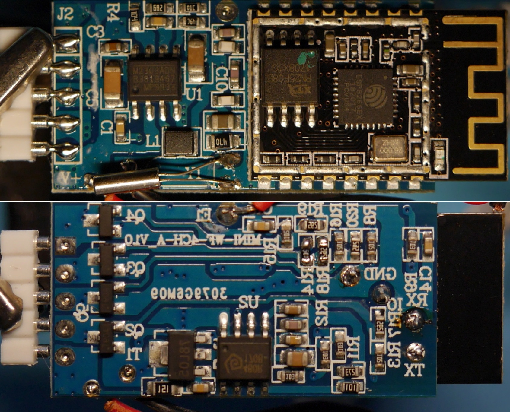
Could you paste here image of the bottom of your board?
I got similar thing and flashed it successfully following the guide in wiki of Tasmota firmware.
Mine is basically copy of ARILUX AL-LC10 and it has communication pads on the bottom of the board.
I am using PlatformIO for building FW and flashing it, and so far didn’t have any issue with it, so highly recommended.
Here is my board:
BTW: I am struggling with making RF controller to work. Could you check which RF chip is on original Arilux board, so I have some comparison?
I just got LC01 from banggood. the mentioned pin config is wrong in mine it work if defined as this. the green and blue pin is swapped.
#define ARILUX_RED_PIN 5
#define ARILUX_GREEN_PIN 12
#define ARILUX_BLUE_PIN 13
and this is my configuration.yaml and work controlling the light without discovery
i just flash my with tasmota but i dont know what to put on yaml file can you share your config. thanks
light:
- platform: mqtt
name: “Sonoff”
effect_list:
- 0
- 1
- 2
- 3
- 4
state_topic: “stat/sonoff/POWER”
state_value_template: “{{ value }}”
command_topic: “cmnd/sonoff/POWER”
brightness_state_topic: “stat/sonoff/DIMMER”
brightness_command_topic: “cmnd/sonoff/Dimmer”
brightness_value_template: “{{ value_json.Dimmer }}”
brightness_scale: 100
rgb_state_topic: “stat/sonoff/COLOR”
rgb_command_topic: “cmnd/sonoff/Color2”
rgb_value_template: “{{ value_json.Color }}”
effect_command_topic: “cmnd/sonoff/Scheme”
effect_state_topic: “stat/sonoff/SCHEME”
effect_value_template: “{{ value.Scheme }}”
retain: true
qos: 1
payload_on: “ON”
payload_off: “OFF”
Make sure you enable SetOption 4, 15 and 20
thanks for the replay can you elaborate on the setoption 4 15 20