DIY Inductive Zigbee water meter

In this forum you find many water meter setups, but they are all based on ESPHome/Wifi. I have a very poor wifi signal around the water meter and I simply love Zigbee. So based on the inductive sensor and the PTVO firmware I have build a zigbee :potable_water: meter with a CC2530 module.
Please note that I am using zigbee2mqtt.

Connect the sensor to the water meter

Convert sensor output
The inductive sensor needs at least 5V and the CC2530 module 3.3V, moreover the output signal from the sensor is >> 3.3V. This has elegantly been solved by ZTAZ via a 4N35 optocoupler.

Connect the wires

Power & Power down
A 5V DC can be obtained from Power supply and tuned to 3.3v by a buck converter.

Custom firmware CC2530
The CC2530 module is flashed with the great PTVO configurable firmware (Zigbee Configurable Firmware v2.5 – Zigbee Hobbyist. Rock Pi 4 SBC 1 136). Flashing is done with the CC debugger and the free software from TI (FLASH-PROGRAMMER Software programming tool | TI.com 26) not V2.
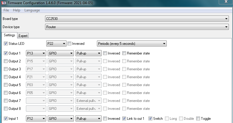
Flash the CC2530 with the following configuration:

HA configuration

The water meter sensor is in fact just a switch. After pairing the PTVO device the switch will appear as:

switch.0x00124b0009d47ac9_l1

Of course this 0x00124b0009d47ac9 will be different in your case :stuck_out_tongue:

The creation of the actual water meter counter is dead simple, just add this to the configuration file:

counter:
  water_meter:
    name: Water meter
    icon: mdi:water
    initial: 560193
    step: 1

Now we have to make the water meter count by this automation:

- id: 'watermetercounter'
  alias: "Water meter"
  trigger:
    platform: state
    entity_id: switch.0x00124b0009d47ac9_l1
    to: 'on'
  action:
    service: counter.increment
    target:
      entity_id: counter.water_meter  

It is also nice to follow the hourly, daily, weekly data. A piece of cake with the standard tools in HA. Add this to the configuration file:

utility_meter:

  hourly_water:
    source: counter.water_meter
    cycle: hourly

  daily_water:
    source: counter.water_meter
    cycle: daily
   
  weekly_water:
    source: counter.water_meter
    cycle: weekly
    
  monthly_water:
    source: counter.water_meter
    cycle: monthly    
   
  yearly_water:
    source: counter.water_meter
    cycle: yearly    

The output looks like this:

Screen Shot 2021-05-01 at 20.31.32

That’s all :wave:

To get the data in the HA energy dashboard 2022.11 add this sensor:

template:
  - sensor:
      - name: "Water m3"
        state: "{{ states('counter.water_meter')|float(0) / 1000.0 }}"
        unit_of_measurement: mÂł
        state_class: total_increasing
        device_class: water
      
13 Likes

Great to see some cc2530/ptvo stuff being built!

EDIT: Don’t do this. See posts below.

You can considerably simplify that circuit as the black wire is an open collector NPN output.

Remove the optocoupler and resistors and connect the black wire directly to P12. Connect the 5V GND to the 3.3V GND if they do not have a common ground.

Leave your CC2530 configuration exactly the same.

The black wire will normally be open allowing the internal pull-up resistor to pull P12 to 3.3V. When active the NPN transistor black wire pulls this to ground. Exactly the same as your optocoupler was doing.

1 Like

If you conect the LJ18A3-8-Z/BX directly to the CC2530, it will fry the zigbee module. The voltage from the black wire is +/- 5v and drops to 0,6 v when the sensor is close to a metal surface. So I would not recommend this.

Nope. It’s an open collector output.

It is either shorted to ground or open circuit.

No voltage.

Datasheet (PDF)

1 Like

OK, so there is a datasheet and real life data. I connected the LJ18A3-8-Z/BX to 5 volt and measured the voltage on the black output wire with the above mentioned results… (5v - 0,6v)

It wouldn’t be the first time a Chinese datasheet was misleading.

If it does have an internal pull-up resistor to the Brown wire you could use a rsisitive divider to drop the 5V to 3.3V or for one less part, just a diode.

5V from the sensor is blocked by the reverse biased diode, and P12 is pulled up to 3.3V by its internal pull-up resistor.

0V / 0.6V from the sensor pulls P12 low.

49518cf5bd5ea508749394f9c31fba08962a987b_2_666x500

2 Likes

Hello, this looks absolutely great, but wanted to point something out here.
It turns out that in NL some areas are starting to implement watermeters that do not have this “metal top” anymore on the red spinning disk. E.g. Brabantwater now deploys a Honeywell meter with so-called eSens technology.
This can be seen clearly because the red spinning disk does not have this metal plate anymore and is “all red”.
I have tried several things, but not yet able to pick up any signal from the meter.

So, hopefully at some point I will be able to solve this (or if someone has an idea??)

image Is this your meter? There seems to be a metal part?

disk

I got the meter exchanged recently and contacted BrabantWater regarding the “missing metal plate” and I got conformation this is intentional and these meters will be used “going forward”.

Eventually they and other “waterschappen” would switch because Honywel also has a “pickup device” that can be added later.

the picture is from Internet, I did not “demolish my meter” to get to the disk :wink:

Is it possible to buy this component already assembled by you? Greetings

1 Like

No I am sorry, no time, but this person [email protected] is selling the fully mounted pcb (see P1 monitor watermeter | ZTATZ in dutch). Perhaps he can help?

sorry that this is a bit off topic. But somehow I caught you on PTVO site and for that reason I want to ask how you connect your I2C sensor using the firmware? please help me. I am using SHT21

Does this help? Search Results for “i2c” – Zigbee Hobbyist. Rock Pi 4 SBC

Am trying to build a water meter and run into this excellent post.
But I am wondering why you did not use the counter feature of PTVO?
Isn’t there a risk that pulses get lost by sending each pulse to HA?

With a Zigbee network protocol it is very unlikely that you miss a pulse. This is confirmed by my data: comparing de HA counter and the real water meter counter.

If you have a power failure of the PTVO watermeter, the counter in HA is not affected. However the counter in the PTVO unit is set to zero I guess?

Good point regarding the power failure. I did see a “remember state” checkbox in PTVO but am not 100% is that will store the current counter value in EEPROM after each update.

Can I use this sensor here?:

Looks like a similar proximity sensor, BUT it is more expensive and more bulky. Can you position it above the rotating indicator? Make sure you measure the actual voltage from the sensor before connecting it.

Hi, thank you!
I managed to put it togeather and it works great, however my water meter metal part seems to be too far from the cover to be picked up.
I am wondering if there is a way to make it more sensitive or to use another sensor?
Such as proximity/color or something like that instead of induction?