I thought this deserved a proper link in here since it is hard to find in searches.
This is definitely reserved to tinkerers unafraid to take stuff apart (and potentially break stuff…) and with the know-how to flash a board with an adapter. The board is not especially easy to reach, and it’s easy to break connectors on your way there. Take extra care when it’s time for the side with the screen to come off (although I can confirm the device still works -flashing too- with the screen disconnected… didn’t need it)!
PS: I am not the maintainer of the project.
It’s been pretty awesome to be able to remove yet another external component (Mi Home app/cloud) from my smart home; the last one in my case, yay!
Here is what I used:
Air Purifier 3H (zhimi.airpurifier.mb3) with AC-M6-B01 REV3-BDR board
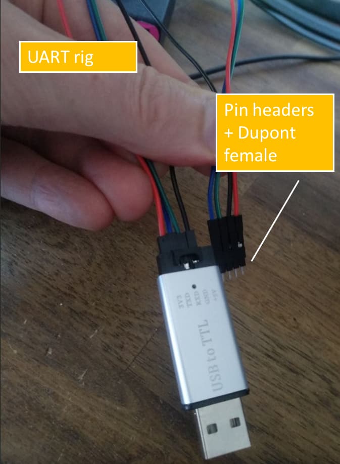
CH340E adapter
External 3V3
With some help from gravity and a couple of well-placed clips with duponts, you can manage to flash the device without soldering anything at all. Everything works as expected; the currently missing sensors (motor rpm, filter use time, etc) I personally won’t miss…
EDIT: A double-beep is mentioned in the README, when the board powers up for flashing; it appears to not always be the case (possibly if beeper disabled before?)… For anyone waiting for them, don’t, it just might be working already; try to flash and see if the serial port opens or not.
My higher capacity Xiaomi does my dining/living room, and I picked up one of these for my bedroom for 100AUD and got it working with Esphome (Tuya MCU).
I came across this custom firmware while searching for a solution to the issues I’ve been having with my 3H (constant disconnections and all). And decided to give it a go, but I can for the life of me figure out the correct way to connect the UART…
Could you please share how you connected the board? Haven’t gathered the courage to ask in the github cause I feel stupid for not been able to figure it out. Anyway, thanks for sharing and for your time!
Take a look at the picture at the bottom of the github readme.
Here is how I did it (can’t promise I didn’t make a mistake though, real or written):
Connect to GND:
GND on serial adapter
grab all below dupont jumpers with alligator clips
pin with GPIO0 arrow, marked 1 on board
dupont jumper M/M
pin next to GPIO0 arrow, marked 2 on board
dupont jumper M/M
pin with GPIO2 arrow
press a dupont jumper M/M on top of the pin and use an alligator clip (preferably with a sleeve, since this is for plastics) to hold it in place with the help of the nearby white connector (should be just close enough)
GND on external power supply
Connect 3v3 to external power supply:
dupont jumper to whatever your power supply offers
had to crank to 3.45v -measured- for it to work
Connect RX/TX to your serial adapter
dupont jumpers according to your adapter
I used pin headers (a 4-pin 2.54mm single row -the ones meant to be soldered-) to plug into the 4 pins (3v3/GND/TX/RX) of the board, with the dupont jumpers on it (jumpers alone could easily touch below the board, pin headers remain parallel!). It will skew a little with gravity (jumpers’ weight), which should ensure continuity.
Ignore the yellow and white wires on the github picture.
Make sure everything is properly connected with a quick continuity test.
There sure are better ways to do it, but I did it with what I had on hand; worked for me… I tried without the external power supply at first, but that didn’t work.
It might seem long “in written format”, but it was actually really fast, and didn’t require messing with the board’s soldering.
Sorry I can’t post pictures, the box is all closed up again…
Just found this amazing item on AliExpress. Check it out! AU$9.57 21%OFF | Cleqee P1512D Mini SMD IC Test Hook Test Leads Kit Mini Grabber Silicone Jumper Wire 26AWG Dupont Cables for Logic Analyzer https://a.aliexpress.com/_mqROGGg
Alright! Can’t believe it was that simple! I would never have thought that I need to ignore the yellow and white wires on the github picture… That was the only part that was bugging me.
Worked like a charm! Thanks for the help and the clear instructions!
Here’s to never having to open those purifiers again! Cheers!
I reckon I got quite lucky and got mine flashed 1st shot just using the ttl adapter for power. I mostly followed your method. I was connected to my HA server (old laptop).
I thought I’d take some flicks to contribute to making the flashing easier to follow for others.
I managed to flash using only dupont cables and pin headers. No soldering or even clips! I had these but they were no good for gpio2 so I abandoned them.
Fantastic, the only thing I missed when I posted… unfortunately mine was already flashed and repacked by then. Thanks.
As I mentioned before, using a power supply, it wouldn’t cooperate until I let the decimal point go up a bit (3.45V), so maybe a USB adapter a bit more lax on the power it lets flowing through works just fine here, without external power. I just tested mine, it outputs near exact, 3.305V.
I measured ~3.3V on mine. Could also possibly depend on how good your connections are and length of wires? Could be some extra resistance/voltage drop if your connections aren’t great etc? I was thinking about this power issue as I went and used as short wires as possible etc. Possibly also an area that might benefit from a soldered approach. Especially if you don’t have a variable power supply (I don’t).
Esp32 can be picky regarding power supply - it must be powerfull enough, since current spikes can be well over 1A. So, if you have some small (or cheap) PSU this could be the problem. If i program my esp32 it won’t program when powered via (low power) usb port… it must be USB3.0 .
I used USB-C (newer adapter), yet no joy… So I think the source of the issue is weirder than that.
But then again, between the computer, drivers, power saving features, the quality of the adapter, connections, and everything else on the board’s side… so many things involved
They also mention a double-beep in the README, when the board powers up; even though I flashed it successfully, I never heard those… In case anyone is waiting for them, don’t, it just might be working already (try to flash and see if the serial port opens). Guessing there could be slight differences between versions/locations…
I just remembered: a while ago i decided to play with newly arrived wemos d1. I coudln’t get it to flash - it didn’t even start to flash. After a while i managed to solve it by (re)installing original wemos drivers on my windows 11, although drivers were installed, i flashed naords with same uart chio before… perhaps fake chinese uart chip…?
Good point. I can’t remember what state it was before I flashed it (had done a bunch of resets & reconfigs…). I updated the original post to mention this. Thanks.