I’m new to MODBUS and trying to figure it out but from a very particular use-case scenario. I just installed a bigger solar controller which uses RS485 and MODBUS to report data. I did a bunch of search on here and other places and I think I understand what is supposed to happen but I can’t figure out how to make it happen.
Goal: Get the solar data from the controller and into Home Assistant.
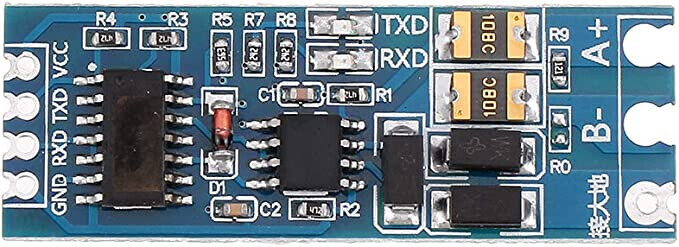
Method: Preferably via ESP32 (or ESP8266 but it seems software UART can be an issue) and RS485 to TTL board. I have both the C25B and auto flow-control versions on hand.
Info gained so far:
I know a bunch of guys have done this already for other solar controllers and I have tried to use as much of their work to learn as I can. The issue there is that each controller (slave device) uses different parameters and I cannot find anything on the Ampinvt controller for this use case.
I watched a video on Youtube where a guy named Antony Cartwright explains there is an issue with ESP32 MODBUS implementation but his video was above my knowledge level.
I know that I need to send a command from the ESP32 (master) to the controller (slave) in order for the controller to send the data back to the ESP32.
I have the MODBUS data sheet from the manufacturer here.
I can see the ESP32 sending the uart.write command but I’m getting nothing back at all from the controller in response. I do, on occasion, get a bunch of zeros.
My current thought is that I have no idea if the uart.write command is correct. I’m trying to learn about registers etc. but the knowledge online is very generic and I suspect that there is a very definitive aspect to this that is not ordinary. While I continue down that path, I figure I’d ask the hive-mind here if anyone can share suggestions.
Seems like I have got a little further and I’ve tried a couple of different options with the basic modbus controller sensor commented out and the custom command version running currently:
From the modbus protocol doc for this unit linked in post #1, I really don’t know what to enter into the custom command. As far as I can figure out, I enter the unit address (0x01) and the master device query command 0xA1. The post you linked to has a bunch of other stuff but they are writing to registers whereas I just need to read.
I tried just adding the byte number in the address: field but that gives a checksum error. Should I be converting those to hex? For battery voltage, 32 is the high byte and 33 is the low byte.
So, reading through the linked post again and trying to figure out the rest of teh custom command, I changed that section to read:
  - platform: modbus_controller
    modbus_controller_id: ampinvt
    name: "Battery Voltage"
    id: battery_voltage
    # custom_command to read Ampinvt registers
    # device slave address: 0x01
    # master device query command:0xA1
    # commmand register 32 (MSB) decimal: 0x20
    # number of registers to read: 0x0001
    # number of bytes: 0x02 (1 parameter x 2 bytes)
    custom_command: [ 0x01, 0xA1, 0x20, 0x0001, 0x02 ]
    value_type: U_WORD
which results in the following in the log:
[17:12:16][V][modbus_controller:159]: Updating modbus component
[17:12:16][VV][modbus_controller:163]: Updating range 0xFAFE
[17:12:16][V][modbus_controller:126]: Range : FAFE Size: 1 (0) skip: 0
[17:12:16][V][modbus_controller:036]: Sending next modbus command to device 1 register 0xFAFE count 1
[17:12:16][VV][uart.arduino_esp32:150]:     Flushing...
[17:12:16][V][modbus:205]: Modbus write raw: 01.A1.20.01.02 (5)
[17:12:16][V][modbus_controller:465]: Command sent 0 0xFAFE 1
[17:12:16][D][uart_debug:114]: >>> 01:A1:20:01:02:BB:A7
[17:12:16][V][modbus:058]: Modbus received Byte  1 (0X1)
[17:12:16][V][modbus:058]: Modbus received Byte  161 (0Xa1)
[17:12:16][V][modbus:058]: Modbus received Byte  32 (0X20)
[17:12:16][V][modbus:058]: Modbus received Byte  2 (0X2)
[17:12:16][D][uart_debug:114]: <<< 01:A1:20:01:02:BB:A7
[17:12:16][V][modbus_controller:036]: Sending next modbus command to device 1 register 0xFAFE count 1
[17:12:16][VV][uart.arduino_esp32:150]:     Flushing...
[17:12:16][V][modbus:205]: Modbus write raw: 01.A1.20.01.02 (5)
[17:12:16][V][modbus_controller:465]: Command sent 0 0xFAFE 1
[17:12:16][D][uart_debug:114]: >>> 01:A1:20:01:02:BB:A7
[17:12:16][V][modbus:058]: Modbus received Byte  1 (0X1)
[17:12:16][V][modbus:058]: Modbus received Byte  161 (0Xa1)
[17:12:17][V][modbus:058]: Modbus received Byte  32 (0X20)
[17:12:17][V][modbus:058]: Modbus received Byte  1 (0X1)
[17:12:17][V][modbus:058]: Modbus received Byte  2 (0X2)
[17:12:17][D][uart_debug:114]: <<< 01:A1:20:01:02:BB:A7
[17:12:17][V][modbus_controller:036]: Sending next modbus command to device 1 register 0xFAFE count 1
[17:12:17][VV][uart.arduino_esp32:150]:     Flushing...
[17:12:17][V][modbus:205]: Modbus write raw: 01.A1.20.01.02 (5)
[17:12:17][V][modbus_controller:465]: Command sent 0 0xFAFE 1
[17:12:17][D][uart_debug:114]: >>> 01:A1:20:01:02:BB:A7
[17:12:17][V][modbus:058]: Modbus received Byte  1 (0X1)
[17:12:17][V][modbus:058]: Modbus received Byte  161 (0Xa1)
[17:12:17][V][modbus:058]: Modbus received Byte  32 (0X20)
[17:12:17][V][modbus:058]: Modbus received Byte  1 (0X1)
[17:12:17][V][modbus:058]: Modbus received Byte  2 (0X2)
[17:12:17][W][modbus:096]: Modbus CRC Check failed! 4858!=201
[17:12:17][V][modbus:058]: Modbus received Byte  167 (0Xa7)
[17:12:17][D][uart_debug:114]: <<< 01:A1:20:01:02:BB:A7
[17:12:17][V][modbus_controller:036]: Sending next modbus command to device 1 register 0xFAFE count 1
[17:12:17][VV][uart.arduino_esp32:150]:     Flushing...
[17:12:17][V][modbus:205]: Modbus write raw: 01.A1.20.01.02 (5)
[17:12:17][V][modbus_controller:465]: Command sent 0 0xFAFE 1
[17:12:17][D][uart_debug:114]: >>> 01:A1:20:01:02:BB:A7
[17:12:17][V][modbus:058]: Modbus received Byte  1 (0X1)
[17:12:17][V][modbus:058]: Modbus received Byte  161 (0Xa1)
[17:12:17][V][modbus:058]: Modbus received Byte  32 (0X20)
[17:12:17][V][modbus:058]: Modbus received Byte  1 (0X1)
[17:12:17][V][modbus:058]: Modbus received Byte  2 (0X2)
[17:12:17][W][modbus:096]: Modbus CRC Check failed! 4858!=201
[17:12:17][V][modbus:058]: Modbus received Byte  187 (0Xbb)
[17:12:17][D][uart_debug:114]: <<< 01:A1:20:01:02:BB:A7
[17:12:17][D][modbus_controller:032]: Modbus command to device=1 register=0xFAFE countdown=0 no response received - removed from send queue
I think what I am doing is adding the hex address of the high (MSB) address at byte 32 (0x20), reading one register with 2 bytes (32 and 33). Clearly, that is not what I’m actually doing but I can’t figure out why.
" The Modbus Polynomial is 0xA001, but to calculate the Modbus CRC in the 'K40 you have to use the bit-reversed value 0x8005 ."
So you will need to do all the coding stuff.
You shoul got a big response per command.
Data validation is performed using ADD8 CheckSum, the sum of all bytes is calculated, and the low
byte data is used as the checksum. The data participating in the check is the entire content of one
frame of data. (does not include the check value itself), the check value is placed in the last 1 byte of a
frame of data.
4、Using a simplified protocol, the communication uses one transmission to exchange data, fixing the
length of each frame of data. The format is: address + command + data + accumulate and check (take
low byte).
5、The Master device queries the MPPT communication interval to be greater than or equal to 1
It seems like the modbus_controller is calculating and adding the checksum as the uart_debug always reports 2 additional bytes of data. If I omit the 5D checksum, the log shows…
01:A1:01:00:00:00:00:2f:71
If I add the 5D checksum, the log shows…
01:A1:01:00:00:00:00:5D:F1:25
Either way, I don’t get a payload and do get CRC check failures.
The Foxess post was where I began the research earlier this week but it makes more sense re-reading it now I am further along the learning journey. The post from @assembly on the deep sleep might also be a factor here so as it is night time and I have 10cm of snow on my panels, I’ll cease working on this until tomorrow and check that out.
As @nikito7 wrote, you’ll have to use uart.write to send this fixed command string.
Your device is using a proprietary protocol with alternative CRC ckeck. The custom_command will calculate and add the 2 byte CRC checksum itself and hereby render useless in this usecase.
You could do something like this instead and use the time component to issue the command at intervals:
Hi. I haven’t read the entire thread, but had a quick look at the protocol.
It doesn’t seem to be standard modbus, so you probably won’t be getting very far with the esphome modbus component.
Instead try setting up a custom uart device. For testing purposes you could also try the custom uart text sensor, which is a bit simpler to set up.
As the 0xA1 query command for each device is fixed and doesn’t change, a simple uart.write should be sufficient. The device will always reply with a fixed length 93 bytes reply.
To parse the reply I would build a custom component to target out the specific bytes needed and publish those. Similar to the projects we’ve done (Foxess, Delta Solivia)
Last night, I got to the stage that @htvekov posted above, abandoning the Esphome modbus and using the uart.write command which is where I started out from after seeing it in other threads for the Foxess and Delta Solivia.
My code section now is as follows:
uart:
  id: mod_bus
  tx_pin: 17
  rx_pin: 16
  rx_buffer_size: 1024
  baud_rate: 9600
  parity: NONE
  stop_bits: 1
  debug:

time:
  - platform: homeassistant
    id: esptime
    on_time:
      - seconds: 15
        then:
          - uart.write: [ 0x01, 0xA1, 0x01, 0x00, 0x00, 0x00, 0x00, 0x5D ]
switch:
  - platform: gpio
    pin: 4
    name: "Solar Controller Writing mode" #if "on" reading from inverter doesn't work!
    internal: true #switch is not exposed to HA frontend, should you ever need to write to the inverter, just comment this line
A couple of notes on it:
If I include the - platform: sntp in the code block, Esphome won’t validate. As far as I can see, the time command will pull from either homeassistant or sntp but not both. I used homeassistant and it seems to be working OK with a uart.write every minute.
Using the checksum calculator, I get a checksum of 5D but in the document from the manufacturer, they use (Page 5, Note 2) A3 in the checksum position. I do not know why and I have tried both 5D and A3 with the same result, which is no response.
I have bright sunshine and clear panels today and I’m still not getting a response so I don’t think the issue lies in a deep sleep state as @assembly identified in his topic.
At this stage, I’m thinking that I have a hardware issue so I’m going to build a duplicate setup using the board with auto flow control identified by @nikito7. I’ll get back to you with results.
The RJ-45 pinout is listed as 1=485+, 2=485-, 7=VCC, 8-GND. The VCC is 5v. On the hardware I have, I am drawing 12v, using a step-down DC-DC to 5V and tying the grounds together. I think I might just build using the 5V from the controller and simplify it.
The platform for time component is not important. Homeassistant will do just fine
A bit odd with the checksum. On same page there’s another example with MPPT #03
.(If you query No.3 MPPT, format is:0x03 0xA1 0x01 0x00 0x00 0x00 0x00 0xA5
I searched a bit and found that they’re using CheckSum8 Modulo 256 and not CheckSum8 2s Complement as I actually expected. Both crc examples in doc checks out fine using this online crc calculator
So checksum in documentation is ok I guess and code should be revised accordingly.
Your problem with no replies could very well be hw related. I’ve only used rs485 ttl modules with hw controlled flow direction. Any led’s on the module that indicate bytes being sent/recieved ?
Are you certain that both MPPT number and uart settings match the actual device configuration ?
I don’t think I’m certain of anything! LOL! I guess that is a good thing and I consider everything to be a cause of potential errors. The MPPT controller is set to address 1 and the docs confirm that it is acting as a slave so I’m pretty sure that the 0x01 address in the command is correct.
The board you show there is the one that @nikito7 recommends but is not the one I am currently using so I just finished up making a master with that one. Do you happen to know if pin 17 on the ESP32 (TXD) connects to TXD on that RS485 board or does it go to RXD on the RS485? I know that it can be trial and error. My install is on a building 300m away, not on the desk next to me.
I believe it’s tx to tx and Rx to Rx between the esp and rs485 module. I can check tomorrow as my production devices are also located outside my house. But at least not 300m away
Update for today:
Rebuilt the hardware using the auto-flow RS485 but still get no response from the MPPT controller.
I have confirmed with the manufacturer that there is no deep sleep state and the RJ-45 pins I am using are the correct ones.
I am content that the command I’m trying to send to the unit are as correct as they can be.
I have confirmed the unit is set at address 001 and 9600 bps
Next steps:
Until I can get some response from the unit, I’m at a standstill. We are due a decent snowfall over the weekend so I think I’ll pull the controller and put it on the desk here and hook up to it with a PC or RPi and see if I can get it talking.
Good idea to verify the rs-485 is working in another config setup.
Perhaps you could wire up two esp8266 with rs485 modules and let them talk with eachother ?
Any rx/tx led indication when connected to the MPPT unit ?
I have only previously had one issue with the cheap rs485 modules. For some strange, unknown reason, only one of the pcb versions I got of the same module actually worked with my Delta Inverter.
I don’t believe that’s the case at your end (especially if tx led lights up when all is connected and you’re issuing a command), but you never know.
In an effort to move forward, I tried hooking up a Raspberry Pi 4 and using pymodbus but didn’t get anywhere. I also tried using an Arduino Uno but couldn’t figure that out either; I can get it to write commands but not show any feedback from the controller. I ordered a USB to RS485 cable so I can use some Windows tools for debugging but that won’t arrive for a week.
The Arduino foray caused me to think about the communication line and I started thinking that in the YAML code above, I am writing to the uart but not reading from it and if I’m not reading from it, how would it display in the log? A little research on uart reads in Esphome led me to the custome UART Text Sensor. A quick copy/paste and a couple of changes and I am now seeing responses in the log window. Progress at last!
I now need to make sense of the output but I confirmed the output is coming from the controller by changing the A3 control code to A1 (that delivers the full register dump so a much longer hex string than A3) and it does indeed change as expected.
Once I get this figured, I’ll go ahead and make it available for others as you guys have done.