Podpoint rate of charge modification for Solar PV

I’ve moved this over from the main podpoint integration thread to avoid cluttering up the work that @mattrayner has done on the integration:-
https://community.home-assistant.io/t/pod-point-ev-charger-integration/307702

Ok. Here’s the breakdown of the mod that I completed this afternoon:-
Usual caveat - anybody should be aware of the risks of operating on high voltage equipment and this will obviously void any warranty with podpoint!

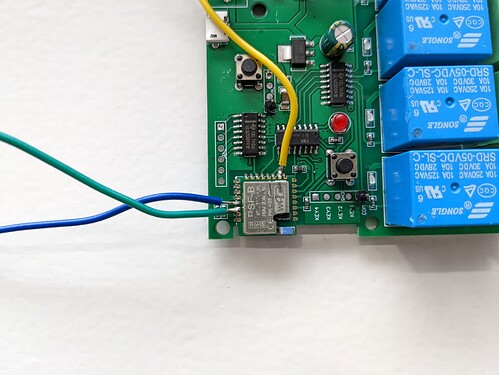
I purchased a cheap esp8285 based 4ch relay from amazon:-
https://www.amazon.co.uk/gp/product/B07JPL78KQ/

There’s no easy header pins on this thing, so you need to solder direct to the chip for the flashing. You need GPIO0 and RX and TX. The 3.3v and GND can be found on two pads you can stick header pins into:-

I flashed it with ESPhome and used the Sonoff 4Ch Pro as a base - the relays seem to be on the same GPIOs:-

esphome:
  name: podpoint-control
  on_boot:
    - switch.turn_on: relay1
    - switch.turn_on: relay2
    - switch.turn_off: relay3
    - switch.turn_on: relay4

esp8266:
  board: esp8285

wifi:
  ssid: "YOUR_SSID"
  password: "YOUR_PASS"
  fast_connect: true
  

captive_portal:

# Enable logging
logger:

# Enable Home Assistant API
api:
  password: "YOURS TO CHOOSE"

ota:
  password: "YOURS TO CHOOSE"

select:
  - platform: template
    name: "Podpoint rate of charge"
    id: 'roc'
    optimistic: true
    options:
      - '1.4 kW'
      - '2.4 kW'
      - '3.1 kW'
      - '3.7 kW'
      - '4.8 kW'
      - '6.0 kW'
      - '7.2 kW'
    initial_option: '7.2 kW'
    on_value:
      then:
        - if:
            condition:
              lambda: 'return id(roc).state == "1.4 kW";'
            then:
              - switch.turn_off: relay1
              - switch.turn_off: relay2
              - switch.turn_off: relay3
        - if:
            condition:
              lambda: 'return id(roc).state == "2.4 kW";'
            then:
              - switch.turn_off: relay1
              - switch.turn_off: relay2
              - switch.turn_on: relay3
        - if:
            condition:
              lambda: 'return id(roc).state == "3.1 kW";'
            then:
              - switch.turn_off: relay1
              - switch.turn_on: relay2
              - switch.turn_off: relay3
        - if:
            condition:
              lambda: 'return id(roc).state == "3.7 kW";'
            then:
              - switch.turn_off: relay1
              - switch.turn_on: relay2
              - switch.turn_on: relay3
        - if:
            condition:
              lambda: 'return id(roc).state == "4.8 kW";'
            then:
              - switch.turn_on: relay1
              - switch.turn_off: relay2
              - switch.turn_off: relay3
        - if:
            condition:
              lambda: 'return id(roc).state == "6.0 kW";'
            then:
              - switch.turn_on: relay1
              - switch.turn_off: relay2
              - switch.turn_on: relay3
        - if:
            condition:
              lambda: 'return id(roc).state == "7.2 kW";'
            then:
              - switch.turn_on: relay1
              - switch.turn_on: relay2
              - switch.turn_off: relay3
        

switch:
  - platform: gpio
    id: 'relay1'
    name: "Podpoint Control Relay 1"
    pin: GPIO12
    internal: true
  - platform: gpio
    id: 'relay2'
    name: "Podpoint Control Relay 2"
    pin: GPIO5
    internal: true
  - platform: gpio
    id: 'relay3'
    name: "Podpoint Control Relay 3"
    pin: GPIO4
    internal: true
  - platform: gpio
    id: 'relay4'
    name: "Podpoint Enabled"
    inverted: true
    pin: GPIO15
    internal: false
    

When I was happy with the code I whipped out the board from the podpoint. You need to disconnect the LED, the wifi antenna and the EM clamp along with the mains in, the charger LIVE/ NEUTRAL / EARTH (if it’s tethered) and the ev data connector. But it’s just 4 screws holding it to the box.

I switched the top 3 dip switches off and then soldered on some pin headers - will make it super simple to rip it out in future.

The relay board connects to a 12v and ground on the podpoint board. I’ve popped all switches 1 2 and 3 on to the NO side of the relays, although thinking about it you could probably do this better by adapting the code and the wiring to failsafe to 7.2kW.
Relay 4 is connected NO to the 2 bottom pins on the podpoint board that are used for the lock. When bridged, the podpoint is locked. You can plug it in but it won’t start until ‘unlocked’ - so this is great for scheduling, etc.

Finally what to do with the relay board. Well it’s a bit of a bodge, but for now, I just cable tied it hanging off the incoming earth cable. It’s not like the box is shaken about all the time, so I don’t think I’ll bother tidying it up any further.

Back in HA and I get the following entities:-

It seems you can lock up the charger if you jump about wildly in rate, but if you increment or decrement through the steps it doesn’t seem to mind.

Biggest issue is that the 1.4 kW doesn’t seem to work. I can only get as low as 2.4 kW - would be interested to know if this is an issue with my charger or if nobody can set the thing to 1.4 - the relays are all working fine and the rest of the options seem to work ok. It’s frustrating as I can see with excess solar you’ll most likely want that lower power setting available.
*EDIT - Ok, so if you switch dip switch 4 to the OFF position (disabling the external energy monitoring), it seems 1.4 kW starts to work. I’m not too worried about the rest of my use causing an issue but I suppose with em monitoring of the house it would be relatively trivial to automate something in HA to lower the rate if the house usage was too high.

I didn’t get to answer my own theory about variable resistors on the board - I didn’t really get enough time to dig into it properly.

My solar is installed on Tuesday, so we’ll see whether it offers some use or whether I need to bite the bullet and buy a zappi.
4 Likes

So update:- I’ve swapped it over for a zappi!

All the above does work. I had a node-red flow that used sensors from my solar integration to determine excess and then switched the podpoint accordingly. I had it poll every 60 seconds. When a rate change was necessary I ended up switching off for a few seconds while the rate change was made as occasionally it was locking up if you did it during charging. I have managed to not need to pay for any charging this way for a few weeks, but there was still loads of excess going to the grid as the rate of charge options are just not variable enough.

By happenstance my parents are moving to another property with an id3 and need a charger, so the podpoint will move over there.

The Zappi went in this afternoon and is so much better suited to the task.

Out of curiosity, did you do the swap yourself?

The newer solo 3 does not have the dipswitch, but charging load can be set via the API. Maybe that can be reversed engineered. It still won’t be as good as the zappi, for sure.

Yeah. It was relatively painless as the podpoint installer had entered from the back. Excuse me!
Otherwise you’ll need to mess about with glands. The cable was silicone sealed so I did the same for the zappi after I’d cleaned it up. The CT for the podpoint seemed to work with the zappi but I swapped them over anyway just to be safe. Biggest issue of concern is just making sure you sufficiently torque the mains terminals.

The original podpoint installer hadn’t done so in my distribution box and I ended up with this.


To their credit they came and rectified immediately and were apologetic. The podpoint rcbo is overspec for the zavvi which has built in RCD protection, but will work fine.

1 Like

Sorry to resurrect this so much later - I’m interested in doing this having just installed solar. With needing live control due to Octopus Agile I had already rigged up our podpoint with a pair of relays (one on the lock pins and one on the 12v CP line as I was told some cars can fail to start charging with just lock pin changes). I’ve ordered a board with more relays - how exactly were you doing “live” changes - lock, change DIP switches, unlock? What kind of timings? Thanks for any info.

Heya. I’m sorry I can’t remember exactly how long I was delaying, but the procedure was lock, and then delay as little as 2 seconds, then dip switch changes, then 1 second and unlock.
I’d suggest starting from there and if it starts to lock up then maybe increase it a little more.
Good luck!

Thanks - I’ll give it a try. I’d imagine I’ll mostly use it as a trickle charge for the car anyway so it’s more about having the ability to slow-charge during the day when there’s excess sun but still charge at 7kW overnight.

Yeah - it should be pretty good with that. If you have a home battery, you could set something up like I have with my immersion heater… Because it’s capped at 3.6kW I have it come on if the battery reaches 100% and solar is more than 1kW - then it goes off if the solar drops below 1kW or the battery depletes to below 80% (or target temperature is hit obviously).
I did the sums on the eddi and just couldn’t justify it.

Hi, I’m the creator of the Pod Point home assistant integration, I’m interested in adding the ability to change the charge rate via the integration (and API), for those who have the pods without dip switches, do you see the option in-app to change it? If not, do you have any examples of changing it via the API?

Hey matt. Wouldn’t that be awesome.
Yeah - that’s exactly what I looked for in the API before I did the dip switch solution, but I didn’t find anything. I guess it’s possible they changed it since last year, but I doubt it. I suspect they’d rather it not be a user configurable option as they’d be worried about hundreds of calls from people who’ve accidentally changed their settings.

FWIW, I happen to have an older Solo and I am pretty sure that Pod Point technical support could remotely alter the charge rate. I had some issues when my solar system was first installed, and Pod Point were able to make a number of adjustments including some that affected its peak charge rate, all done remotely with no engineer attending. Of course that may not be via any public API, sadly, but worth anyone that wants it hassling them, may eventually get something bumped up a todo list…

Hi all, i know this threadis a little old but i’m hoping someone can help. i’ve been working on a similar solution controlled via my Home inverter charger unit that will combine the solar panels and battery bank. the issue that i have is that my dip switch don’t seem to function. i’m assuming they’re been over written by the podpoint server. does anyone know how to get them working or factory reset the charger?