Power Flow Card Plus šŸš€

Any idea why after upgrade, gas rate is showing incorrectly on the power flow card?


Iā€™m not seeing anything that could be causing this here in Code Editor either:

    - entity: sensor.gasmeter_rate_per_time_unit
      calculate_flow_rate: true
      inverted_animation: true
      decimals: 2
      icon: mdi:gas-burner
      use_metadata: false
      name: Gas
      unit_of_measurement: mĀ³/h
      display_zero: true
      secondary_info:
        entity: sensor.gas_cost_daily
        decimals: 2
        display_zero: true
        unit_of_measurement: ā‚¬
        unit_white_space: true
      display_zero_state: true
      show_direction: false
      unit_white_space: false
      color_value: false
      color_icon: false
      display_zero_tolerance: 0

Love the new update. Thank you guys.

Let me adress one whish of my inner design monk.

Can the secondary info get the same color like the circle? Or a dedcated color attribute? Should be similar to the battery circle, where the upper info is colored instead of being default color.

image

I pretty much like the PFC and also take advantage of the new feature for individual bubbles.

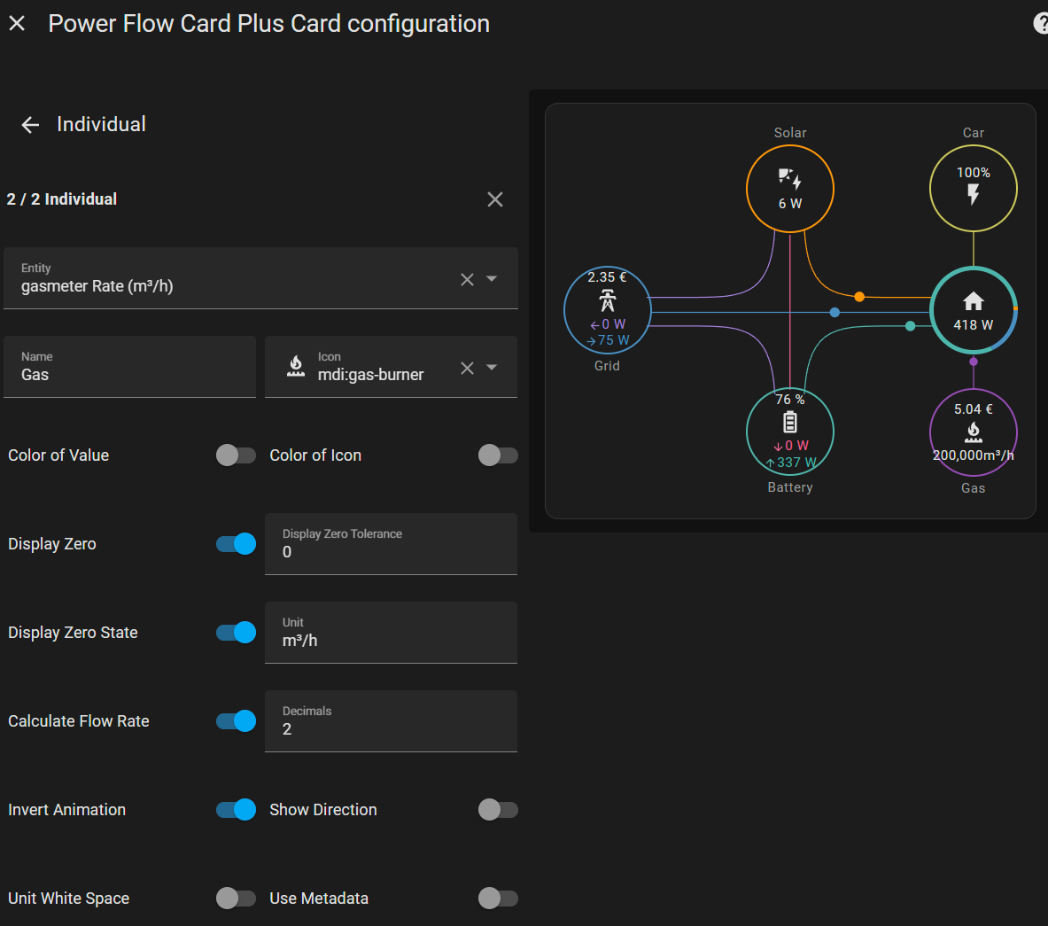
However I have a problem with secondary information of type text - it is not shown anymore or I am missing some configuration which needs to be done.

I tried to show in a minimal example - both ā€œHomeā€ and ā€œIndividualā€ have as secondary information a helper of type text defined, but it is shown only for ā€œHomeā€.
image

type: custom:power-flow-card-plus
entities:
  battery: {}
  grid:
    entity: sensor.solax_battery_import_from_grid
  solar:
    display_zero_state: true
  individual:
    - entity: sensor.heatpump_total_active_power
      secondary_info:
        entity: input_text.test_text
  home:
    secondary_info:
      entity: input_text.test_text
clickable_entities: true
display_zero_lines: true
use_new_flow_rate_model: true
w_decimals: 0
kw_decimals: 1
min_flow_rate: 0.75
max_flow_rate: 6
max_expected_power: 2000
min_expected_power: 0.01
watt_threshold: 1000
transparency_zero_lines: 0

I have the same issue. No idea why.

Does the power card assume that battery discharge is always to the house? I am currently exporting solar and battery to the grid, but the card assumes solar going to grid, and battery to home which is incorrect. Having two separate entities doesnā€™t help as their are actually three routes for battery: solar/battery, battery/house, battery/grid. Any one help me where I am going wrong?

After the update, I reconfigured my PFCP, but unfortunately, the Grid Battery Charging isnā€™t displaying correctly. Only the grid ā†” Home line is visible.

Hereā€™s my configuration:

type: custom:power-flow-card-plus
entities:
  battery:
    entity: sensor.ladeleistung_dashboard
    state_of_charge: sensor.state_of_charge_vorlaufig
    invert_state: true
  grid:
    entity: sensor.netzbezug_insgesamt
clickable_entities: true
display_zero_lines: true
use_new_flow_rate_model: true
w_decimals: 0
kw_decimals: 1
min_flow_rate: 0.75
max_flow_rate: 6
max_expected_power: 2000
min_expected_power: 0.01
watt_threshold: 1000
transparency_zero_lines: 0

And thats the Result:

image

Anyone has an idea?

Iā€™ve been using the custom power flow card (not this one and also not the built-in one) from soon after the energy dashboard got introduced to HA. Recently, I decided to switch to this card, because thereā€™s also the energy flow plus card to accompany it. This card also allows for the configuring of individual devices, which is nice. My power flow plus card is working fine ā€“ happy with that.

My problems are:

  1. I cannot find a forum thread related to the energy card. Am I just not finding it? I couldnā€™t even find any but one reference to it in this thread. While I see activity on the power cardā€™s repo, it doesnā€™t seem like the energy card has been updated recently.
  2. This brings me to my real issue, which is that I cannot get the individual device config to work.
  3. I also cannot get a line between solar and grid, even though it works for my power flow card.

Due to the lack of options, Iā€™ll post my config here in a best effort to get a response. The docs state an individual1 key and an individual2 key. Itā€™s not clear why there are two keys, compared to the power flow card that has a single individual key with a list of devices (entities). Does this mean the energy card can have only 2 individual devices visualised?

Power on the left, energy on the right:

My energy flow config.
      - type: custom:energy-flow-card-plus
        energy_date_selection: true
        kwh_decimals: 1
        use_new_flow_rate_model: true
        clickable_entities: true
        display_zero_lines: true
        entities:
          grid:
            entity: sensor.daily_grid_energy_consumption
          battery:
            entity:
              production: sensor.battery_energy_out
              consumption: sensor.battery_energy_in
            state_of_charge: sensor.battery_state_of_charge
          solar:
            entity: sensor.daily_solar_energy_consumption
          home:
            entity: sensor.daily_home_energy_consumption
            override_state: true
          individual1:
            - entity: sensor.daily_geyser_energy_consumption
              name: Geyser
              icon: mdi:water-boiler
              display_zero: true
          individual2:
            - entity: sensor.outbuilding_power_meter_channel_1_energy
              name: Outbuilding
              icon: mdi:garage-variant
              display_zero: true
For reference, my power flow config.
      - type: custom:power-flow-card-plus
        use_new_flow_rate_model: true
        clickable_entities: true
        entities:
          grid:
            entity: sensor.grid_power
            power_outage:
              entity: binary_sensor.grid_feed
              state_alert: "off"
          battery:
            entity: sensor.battery_power
            state_of_charge: sensor.battery_state_of_charge
            invert_state: true
          solar:
            entity: sensor.pv_power
          home:
            entity: sensor.home_power
            override_state: true
          individual:
            - entity: sensor.geyser_power
              name: Geyser
              icon: mdi:water-boiler
              display_zero: true
              decimals: 1
            - entity: sensor.outbuilding_power_meter_channel_1_power
              name: Outbuilding
              icon: mdi:garage-variant
              display_zero: true
              decimals: 1
        watt_threshold: 1000
        dashboard_link: /energy

I made some progress:

  1. It seems like this is the place to get help. Still seems odd thereā€™s so little on the forum here.
  2. The individual* keys take objects, not lists of objects (so I simply had to remove the dashes).
  3. Use the split sensor options.

Hi @parautenbach, can you tell me how do you add the Date-Switcher (on top at the right side in you scerrnshot) in your dashboard?

Iā€™m using the built-in one, but thereā€™s also the one by the author of these cards. I tried it briefly, but then stuck with the built-in one.

The built-in one:

type: energy-date-selection
1 Like

Hey there, I really enjoy your card.

But I have one thing, I donā€™t understand.


The value for the ā€œHouse consumptionā€ is always way off (always around factor 2).

In the configuration for the card Iā€™m using only the ā€œHouse consumptionā€ sensor for the home

And in the entity view, Iā€™m also using the same sensor

Is this some kind of a bug, or am I doing something wrong?

Any help is appreciated.

Thanks

What happens when you turn on the override state option? Do you have individual devices configured?

If set to true , the home consumption will be the state of the entity provided. By default the home consumption is caluclated by adding up all sources. This is useful, when for example you are using an inverter and it has power losses.

1 Like

That looks much better now.
I will check it tomorrow when I have some more data.
Thanks a lot :+1:

Hi all,
Iā€™m totally new and noob to the entire Home Assistant stuff, so excuse my stupid questions. This Home Assistant community is so big, and so complicatedā€¦itā€™s like searching for a needle in a haystack. I hardly understand all the coding you guys do, so Github and all that is a bit blurry for me.

My question: I succeeded in connecting my Sungrow inverter to HA, and I see that there are whole lot of entities in that system, but how do I know which entities to use to make the Power Flow Card work? My current card doesnā€™t make any senseā€¦guess i picked the wrong entities? cant seem to find the battery percentage eitherā€¦some guidelines or other links would be nice. Thx

This is my setup (also Sungrow with MKaiser integration)

type: custom:power-flow-card-plus
entities:
  battery:
    entity: sensor.signed_battery_power
    state_of_charge: sensor.battery_level_filtered
    invert_state: true
    color_value: true
    use_metadata: false
  grid:
    entity: sensor.meter_active_power
    name: Grid
    display_state: one_way_no_zero
    secondary_info:
      entity: sensor.utility_meter_daily_calculation_total_exported_energy
      unit_of_measurement: kWh
      color_value: false
  solar:
    entity: sensor.total_dc_power
    display_zero_state: true
    color_value: false
  home:
    entity: sensor.sungrow_load_power_corrected
    color_icon: true
  fossil_fuel_percentage:
    display_zero_state: false
    display_zero: true
    icon: mdi:water-opacity
    color_value: true
    color_icon: true
    color:
      - 3
      - 169
      - 244
    name: Water
    unit_white_space: false
    secondary_info:
      entity: sensor.daily_water_litres
      color_value: false
      icon: ''
      unit_of_measurement: L
      unit_white_space: true
      decimals: 0
    entity: sensor.daily_water_litres
    use_metadata: false
  individual:
    - entity: sensor.hvac
      display_zero_state: false
      display_zero: true
      name: HVAC
      icon: mdi:sun-snowflake-variant
      calculate_flow_rate: true
      color_icon: true
    - entity: sensor.baseload
      name: Baseload
      icon: mdi:power-standby
      color_value: false
      color_icon: true
      display_zero_state: false
      calculate_flow_rate: true
    - entity: sensor.charging_hot_water_240v_greenhouse
      name: Extra
      icon: mdi:sun-clock-outline
      color:
        - 183
        - 127
        - 31
      calculate_flow_rate: true
      color_icon: true
      color_value: false
    - entity: sensor.personal_electronics
      name: Electronics
      calculate_flow_rate: true
      color_value: false
      icon: mdi:desktop-classic
      color:
        - 146
        - 63
        - 63
      color_icon: true
clickable_entities: true
display_zero_lines:
  mode: grey_out
  transparency: 50
  grey_color:
    - 51
    - 51
    - 51
use_new_flow_rate_model: true
w_decimals: 0
kw_decimals: 1
min_flow_rate: 0.75
max_flow_rate: 6
max_expected_power: 2000
min_expected_power: 0.01
watt_threshold: 1000
transparency_zero_lines: 0
title: Current Power Use
disable_dots: false
```u

I wanted to check if this is possible. I have more than a few devices to add but the 4 devices limit is an issue. Is there a way to add more devices but only show the ones which consume more power? Maybe the 4 devices which are consuming more than 1 watt etc.

Basically a conditional view.

Hi,
iā€™ve an issue about gas circle.
Decimals in the circle are wrong because the sensor has another value like the image attached:

Catturafdsssss
Catturafffff

This is my code:

type: custom:power-flow-card-plus
entities:
  grid:
    entity:
      production: sensor.potenza_ceduta_rete_realtime_watt
      consumption: sensor.potenza_acquistata_rete_realtime_watt
    display state: two-way
    name: Rete
  solar:
    entity: sensor.potenza_prodotta_fotovoltaico_realtime_watt
    icon: mdi:solar-panel-large
    display_zero_state: true
    name: Solare
    unit_of_measurement: w
  home:
    entity: sensor.potenza_acquistata_rete_realtime_watt
    name: Casa
    color_icon: solar
    display_zero_state: true
  individual:
    - entity: sensor.alfenwallbox_active_power_total
      icon: mdi:car-electric
      name: Zoe
      display_zero: false
      color_icon: true
    - entity: sensor.daily_gas
      icon: mdi:gas-burner
      unit_of_measurement: mĀ³
      color_icon: true
      display_zero: true
      color_circle: true
      color: red
      name: Gas
      inverted_animation: 'no'
  fossil_fuel_percentage:
    entity: sensor.it_cno_grid_fossil_fuel_percentage
    icon: mdi:leaf
    color_icon: true
    display_zero: true
    name: Low Carbon
    state_type: percentage
clickable_entities: true
display_zero_lines:
  mode: show
  transparency: 50
  grey_color:
    - 189
    - 189
    - 189
use_new_flow_rate_model: true
w_decimals: 0
kw_decimals: 1
min_flow_rate: 0.75
max_flow_rate: 6

Thanks in advance for your support.
Regards,

Alessandro

Hello,

I have 2 inverters of 10kW each. How can I combine the entities so that only the sum of the two is displayed here?

Thank you for your help

Haase

Make a template sensor that is the sum of the two.

Hello,
How do you do that? Iā€™ve never done anything like this before. Are there any instructions?
Thank you