If it doesn’t work then you need to get the last used rolling code from the original D1 mini (or just guess a higher number) and use the set then sync commands to get the new D1 mini to use that counter number.
Certain doors (depending on firmware revision) will not respond to repeated commands. Most of them have a logic board part number starting with 45
Ah okay, so I’m assuming they just wired the two protector systems (obstruction sensors) together in the wall somewhere because near the garage door edges (on the garage door rail), I can see a sensor on each side (two sensors total) which has a pair of wires that run into the wall. However, where the wires come out of the wall near the garage door opener, there’s only one pair of wires for the obstruction sensors and one pair of wires for the garage door opener.
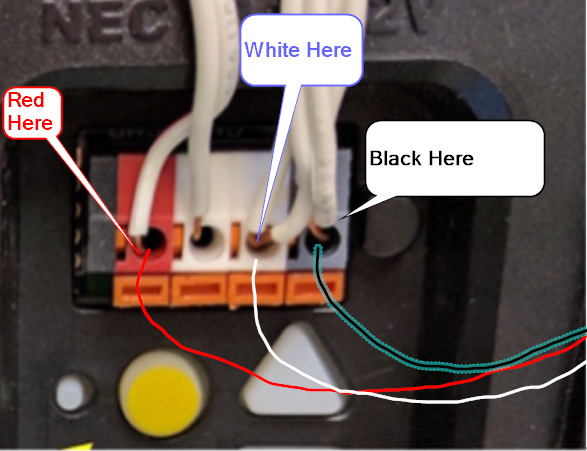
However, what doesn’t make sense is it looks like the wall garage door opener controller is wired to the Red/Ctrl (red port) and Blk/Obst (gray port) on the garage door opener. My understanding is it should be wired to the Red/Ctrl (red port) and one of the Wht/GND (white ports). Here’s a slightly better photo.
Actually, now that I think of it, I’m guessing they just combined the ground wire for the two obstruction sensor and one wall controller into one wire which is plugged into the white port on the garage door opener.
That being said, I’m assuming I can just wire up the Ratgdo like this:
Use a 3-conductor Wago for the Red/Ctrl: one wire going to the Ratgdo, one wire to the wall controller and one wire to the garage door opener
Connect the Wht/GND from the Ratgdo directly to the empty white connector on the garage door opener
Use a 4-conductor Wago for the Blk/Obst: one wire going to the Ratgdo, one wire to the obstruction sensors and one wire to the garage door opener
This is a pretty frequent request. I have to confirm but I think these will be supported by a near future release which adds support for Security + 1.0 openers (the kind which doesn’t use encrypted rolling code and respond to shorting the wires but still communicate via serial over the wall control panel wiring).
I just got a Liftmast opener installed as part of an insurance claim after a water leak and I am interested in applying one of these so I can control with HA. I was wondering though what people options are about using MQTT vs ESPHome? Does one have an advantage over the other?
I have a strange feeling you’re going to see an uptick of orders soon as myq restrictions on their API make it less and less usable. Thanks for the work here.
I ordered a couple of backordered bare ratgdo shields a few days ago as well as a few ESP8266 D1 Wemo clones from Amazon which arrived today.
I have the CH340 windows driver installed, and device manager shows USB-SERIAL CH340 (COM7) when the ESP8266 is connected to the PC.
When I run the web installer, it shows the option: USB2.0! (COM7) - Paired which I select, but this results in the error: Failed to execute 'open' on 'SerialPort: Failed to open serial port.
SOLVED!
I had installed a newer CH340 driver that was the problem. Reinstalled from this source - and problem solved. Ugh, installing zip or exe’s direct from China is scary stuff. It would be a lot more reassuring if ESPHOME or RatGDO would host the vetted driver(s).
I’d like to buy one of these to Finland, but it seems that the order page doesn’t let to choose Finland as shipping destination (always changes back to United States automatically). Any chance to get delivery to Finland? thx
I ordered a (backordered) Ratgdo shield and am going through the wiring documentation. I apologize with how bad I am at understanding schematics, but for the right side of the board (the optional open/close/light/door/obst/ground) are these mandatory to get the status of the door and lights and stuff? Anyone have any pictures of their wiring of these?
I was looking at the conversation on Github and it sounds like the TTC function might be able to be implemented with the existing board design. Is that correct or do you foresee a new board revision?
I have a v2 board that was used for all my TTC dev/testing efforts. I don’t think there is a need for hardware change to implement TTC like a stock wall controller.
@PaulWieland any updates on backorder shipments going out? I’m sure you’re swamped with orders from when the MyQ integration stopped working, so no rush.
Edit: And of course I just realized there’s a message posted on the ratgdo page:
Boards ordered before September 12th will ship by the end of September. Orders received after the 12th will ship by the end of October. After October I expect to be caught up on inventory and will have enough stock to avoid future backorders. Thank you for your patience!
Also, does anyone know what gauge wire the garage door opener wires are? I’m planning on ordering some wire and wago connectors for the install and just want to make sure I get the correct size.
I used 18 gauge furnace wire I had laying around because its solid copper. The garage door wire is solid copper as well and is 20 gauge. I don’t think wago connector is the way to go with wire this thin . I would use small wire nuts or just twist the wires together and use heat shrink ( that’s what I did). I would use solid copper wire if I had it for ease of use.
Sorry Paul had the board upside down not trying give you any support emails apologies. I just removed the board the in incorrect wire picture and added your diagram.


 . I would use small wire nuts or just twist the wires together and use heat shrink ( that’s what I did). I would use solid copper wire if I had it for ease of use.