Project: Tasmota configuration of a standard set up relays L1, L2 or L3 connection and some of the buttons to be used as remote control switch to control other MQTT devices remotely with buttons using Rules.
Sonoff TX T0 switches with one, two or three buttons.
(Sonoff names the TX switches 1 gang, 2 gang and 3 gang)
The T0 is the same as T1 T2 and T3 just different country design, color and NO 433mz RF
more info Sonoff TX switches
Objective:
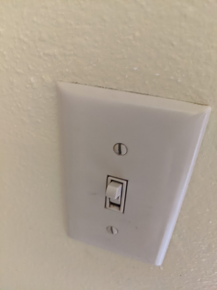
Replacing household single-pole, single-throw Flip switches (SPST)
First location:

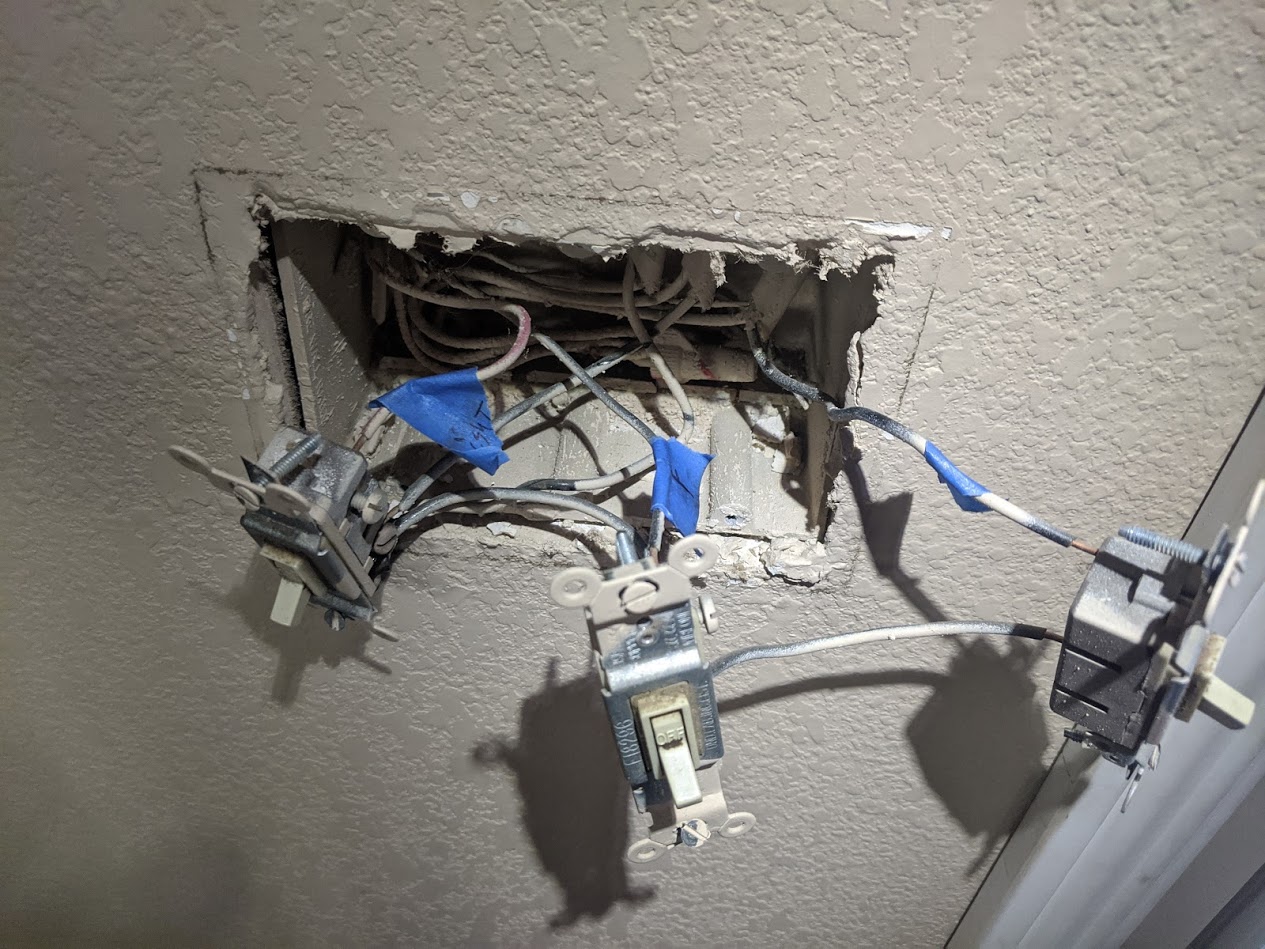
Dining room 3 gang electrical box.
Remove three SPST switches
Wires: L 120V, Neutral, Ground, Light, Fan and Patio.

Replacements:
Dining Room Switch #1 (standard wired direct connect to Dining Room Light, dining room Fan and Patio light.) Not a dummy
TX T0 three button switch:

Wire connections
Lin 120V, Nin Neutral
- button 1 wired to L1 Dining Room Light
- button 2 wired to L2 Dining room Fan
- button 3 wired to L3 Patio light.
Dining Room Dummy Switch #2 (dummy switch only wired to Lin and Nin for device power.) Remote control
TX T0 three button switch:
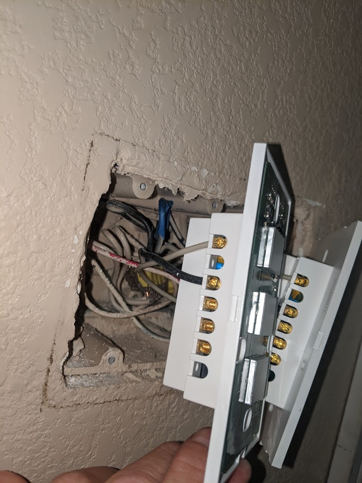
WIre connections
Lin 120V, Nin Neutral, no connections to L1, L2 or L3 relay out.
- button 1 living room Light no connection L1 relay use MQTT Rules
- button 2 living room Fan no connection L2 relay use MQTT Rules
- button 3 kitchen light no connection L3 relay use MQTT Rules
Second location:
Living room 4 gang electrical box.
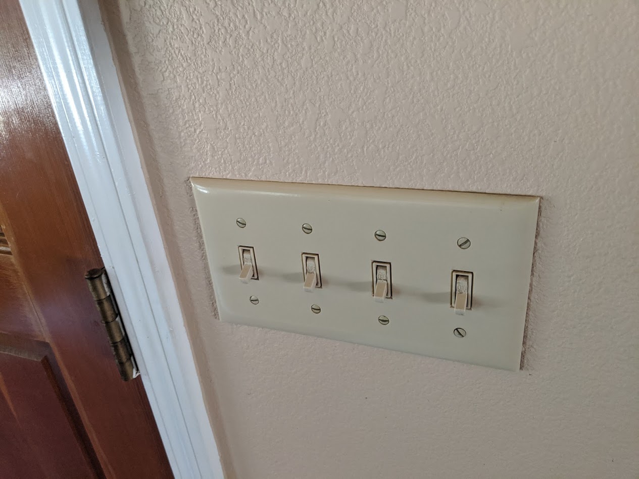
Remove four SPST switches
Wires: L 120V, Neutral, Ground, living room Light ,living room Fan and Porch light.
Removed forth switch and hot wired that toggled a plug.(now always on)
Replacements:
Living Room Switch #1 (standard wired direct connect to Living Room Light, Living room Fan and Porch light.) Not a dummy
TX T0 three button switch:
Wire connections
Lin 120V, Nin Neutral,
- button 1 wired to L1 Living Room Light
- button 2 wired to L2 Living room Fan
- button 3 wired to L3 Porch light.
Living Room Dummy Switch #2 (dummy switch only wired to Lin and Nin for device power.) Remote control
TX T0 three button switch:
WIre connections
Lin 120V, Nin Neutral, no connections to L1, L2 or L3 relay out.
- button 1 dining room Light no connection L1 relay use MQTT Rules
- button 2 dining room Fan no connection L2 relay use MQTT Rules
- button 3 office light no connection L3 relay use MQTT Rules .
Third location:
Kitchen/pantry 1 gang electrical box.
Remove 1 SPST switch
Wires: L 120V, Neutral, Ground, pantry light.
This switch is in the kitchen for the pantry. button2 to control Kitchen light remotely
Replacements:
Pantry Switch (button1 standard wired direct connect L1 to pantry light,)
button2 Remote control Kitchen light)
TX T0 two button switch:
Wire connections
Lin 120V, Nin Neutral,
- button 1 wired to L1 pantry light
- button 2 dining room Light no connection L2 relay use MQTT Rules
Forth Location:
Kitchen 1 gang electrical box.
Remove 1 SPST switch
Wires: L 120V, Neutral, Ground, kitchen light.
This switch is in the kitchen near the door to garage. button2 to control Garage light remotely
Replacements:
Kitchen Switch (button1 standard wired direct connect L1 to kitchen light,)
button2 Remote control garage light)
TX T0 two button switch:
Wire connections

Lin 120V, Nin Neutral,
- button 1 wired to L1 kitchen light
- button 2 garage light no connection L2 relay use MQTT Rules

You get the idea how this works. Below is how to set up the rules for the above TX devices.
I also have a 3 button TX in hallway button1 direct connection to hallway light, button2 living room light, button 3 kitchen lights. Then each bedroom has a TX two button to turn on the lights in room and hallway light.
Now on to rules and settings…
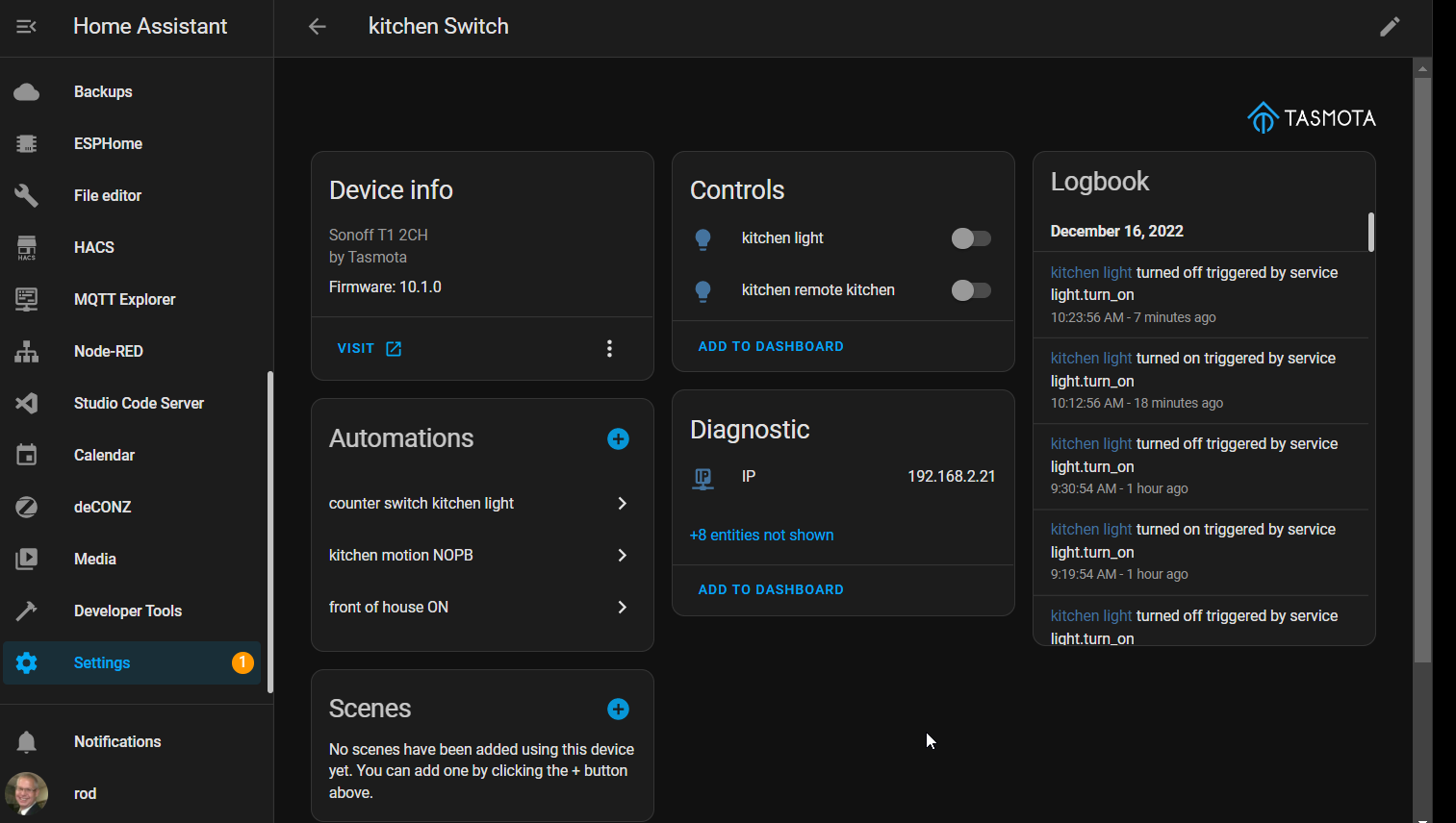
Flash your Devices with Tasmota.
Access each device WebUI by entering the IP address into a browser.

Toggle the dummy switches on or off to set full time brightness of buttons.
Go to configure module and select your device type.
Such as
Sonoff T1 3CH (the 3CH means 3 buttons.)
Configure the name of Device and
Entities (BUTTON/SWITCHES/SENSORS)
carefully so you don’t have to rename to many entities in Home Assistant later and or get confused on what is what device or entity.
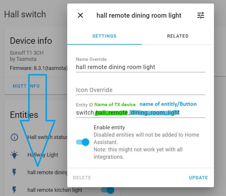
here I named the device and buttons wrong in tasmota settings and had to override name in Home assistant.
Tasmota configure MQTT Tab
Topic: diningroom_switch
Tasmota configure other Tab

Device name:
dining room switchis the name of the device with the buttons.
Friendly name
Is the name of the Entities (buttons,switches or sensors) assigned to the switch GPIOs
- Friendly name 1
dining room light - Friendly name 2
dining room fan - Friendly name 3
patio light
For a switch that will have nothing connected to relay or I call a dummy remote button.
Tasmota configure MQTT Tab
Topic: diningroom_remote_switch
tasmota configure other Tab
Device name: dining room remote switch
Friendly name
- Friendly name 1
diningroom remote livingroom light - Friendly name 2
diningroom remote livingroom fan - Friendly name 3
diningroom remote kitchen light
Or TX switch that will have a mix of live and dummy buttons.
Tasmota configure MQTT Tab
Topic: hallway_switch
tasmota configure other Tab
Device name: hallway switch
Friendly name
- Friendly name 1
hallway light - Friendly name 2
hallway remote dining room light - Friendly name 3 `hallway remote kitchen light’
Set your options and commands in the Tasmota console
![]() BACK UP config FIRST!
BACK UP config FIRST! ![]()
SetOption can now be shortened to SO in 8.3.1
Options that we will be using for this tutorial.
Need to change from default or check if correct.
- SetOption1 ON
- SetOption73 OFF or ON
- ButtonTopic 0
- Setoption13 ON or OFF
To set the options and commands use a backlog
Backlog command allows executing up to 30 consecutive commands with a single command line. Each command is separated by a semicolon (“;”). Backlog is a useful feature to avoid numerous restarts when setting up a new device.
Full documentation of commands here Commands - Tasmota
Input your backlog in the webUI console like this for each tasmotized device
Input into the tasmta webUI console this.
Backlog SetOption73 0; ButtonTopic1 0; SetOption1 1; setoption13 1
If you have more that one button then you need to add buttontopic1;buttontopic2 0 and so on.
Information about settings in above backlog.
SO1 1
default is 0
SetOption1 Set button multipress 4 mode to
0 = allow all button actions (default)
1 = restrict to single to penta press and hold actions (i.e., disable inadvertent reset due to long press)
SetOption73 0
default is 0
Enable Buttons decoupling and send multi-press and hold MQTT messages
0 = disable decoupling (default)
1 = enable decoupling
I found I did not need to set this to 1 (ON) after using my rules in dummy switches (nothing connected to relays). But might have to in some other types of devices.
Buttontopic default
Buttontopic1 0, Buttontopic2 0 and Buttontopic3 0 depending on how many buttons your device has.
= set MQTT button topic
0 = disable use of MQTT button topic
1 = set MQTT button topic to device %topic%
2 = reset MQTT button topic to firmware default (MQTT_BUTTON_TOPIC) (default = 0)
If using MQTT to issue this command, if it is published to the device GroupTopic, the command will not be executed.
When Not using multi press or long press rules I like to use
SetOption13 1
default is 0
Allowing immediate action on single button press Disables long press functions also helps with blocking reset of device with a long press. Faster reaction does not wait for finger to be removed.
For auto discovery If using Home assistant without yaml.
SO19 1
default is 0
*Set after you have your device and all entities named, rules and options set so homeassistant has matching info.
Rules for remote buttons to control other MQTT entities/devices.
A little bit of explaining what each command is and what control relays.
Power Control the corresponding power state (1…8) (also restarts PulseTime)
0 / off / false = turn OFF
1 / on / true = turn ON
2 / toggle = if power state is ON switch to OFF and vice versa
3 / blink = toggle power for BlinkCount times each BlinkTime duration (at the end of blink, power state is returned to pre-blink state)
4 / blinkoff = stop blink sequence and return power state to pre-blink state
Example and definition of POWER:
Default rules and options.
A TX0 is a 3 button switch with 3 relays. By default (sonoff T1 3CH template) Button1(GPIO0) is coupled to the first relay(GPIO12)=(POWER1) Touching the button once will toggle the first relay wired to L1 wire connector.
Touching the button once will toggle the corresponding relay.
In Tasmota
Button1 is the first button of three triggering POWER1 the first relay L1 connection of three.
Button2 is the second button of three triggering POWER2 the second relay L2 connection of three.
Button2 is the third button of three triggering POWER3 the second relay L3 connection of three.
Rules and Options:
With the same device template as above you can set some rules and options.
Long press, multi press and behaviors.
Control other MQTT entities with a switch or button press.

Before doing rules *Check what the order of
prefix/topic or topic/prefix
In tasmota device info or console
by typing in the console
Fulltopic
will look like this or reversed
FullTopic”:"%prefix%/%topic%/
kids_bedroom_light/cmnd/
or
cmnd/kids_bedroom_light/
For each TX switch In the tasmota webUI console type in the rules like this
diningroom remote switch
Rule1
ON button1#state DO publish cmnd/livingroom_switch/POWER1 2 ENDON
ON button2#state DO publish cmnd/livingroom_switch/POWER2 2 ENDON
ON button3#state DO publish cmnd/kitchen_switch/POWER1 2 ENDON
Livingroom remote switch
Rule1
ON button1#state DO publish cmnd/diningroom_switch/POWER1 2 ENDON
ON button2#state DO publish cmnd/diningroom_switch/POWER2 2 ENDON
ON button3#state DO publish cmnd/office_switch/POWER1 2 ENDON
Hallway switch
Rule1
ON button2#state DO publish cmnd/diningroom_switch/POWER1 2 ENDON
ON button3#state DO publish cmnd/kitchen_switch/POWER1 2 ENDON
kitchen_switch
Rule1
ON button2#state DO publish cmnd/garage_switch/POWER1 2 ENDON
pantry_switch
rule1
ON button2#state DO publish cmnd/kitchen_switch/POWER1 2 ENDON
Dont forget to turn on each rule after.
type this is console
Rule1 1
Now you can set auto discovery If using Home assistant without yaml.
type this is console
SO19 1
All your switches will now show up in Homeassistant.


Here is my write up on DEVICE BUTTON WITH 4 DIFFERENT ACTIONS
Tasmota Version 8.3.1 button and switch commands.
EDIT May 28 2020 Added to bottom of post:
Sonoff Touch multiple press and group topic
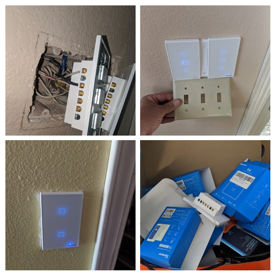
Sonoff TX switch mounting in Multiple gang boxes
I have done blank covers over older single button sonoff touch.

My original plan for this project was to use blank covers and when I get a 3d printer to print custom covers with Icons over buttons.
here is a blank that a carved out squares were buttons are.


She liked the original covers so I just cut down blanks to fill in gaps.
here is a single blank I cut the middle out.
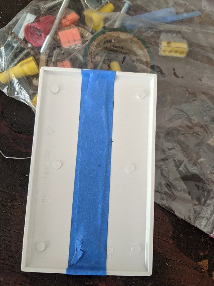

The 4 gang box I was short a TX 3button so for now I just put one swich in and cut down a 3 gang blank to fill in.
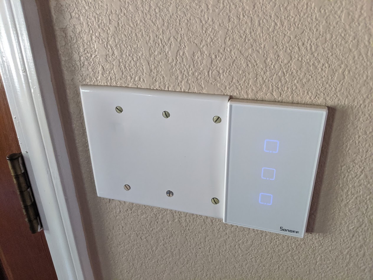
when I add another switch for the dummy switch I will cut down the other side and have filler in the middle.
this winter after I get a 3d printer I will design something nicer.
UPDATE**** January 2021**
Added 7 more sonoff TX switches some were the TX 2 three button with 433mhz option.
Added TX 2 three button to bedroom with a twist. (Tasmota rules to control shelly 2.5 connected in a ceiling fan)

Barbara Flashing her Christmas gifts with Tasmota.

Shelly 2.5 mounted in a fan/light and wall switch control.
Sonoff TX remote dummy switch. NO wires connected to LIGHT/FAN just power and neutral.
Full time power running to Shelly 2.5 installed in fan housing.
Big shout out to @digiblur Travis Griggs digiblur
Most of the Tasmota stuff I learned from his blog and videos.
I was asking him in his discord about using tasmota rules to link up Sonoff switches to a non flashed Shelly 2.5 that is just mqtt setting in ha config.
Long story short he just said just flash
I say “I don’t want to remove from light\fan.”
He said “OTA over the air” and gave me a link to his Video on how to over the air flash Shelly devices with just a web browser.
OTA tasmota shelly devices.
I have to say it was so easy
To do and why in the world would people use Shelly for Hass or even the mqtt config in ha?
It took me 5 minutes to over the air flash and configure the 2.5 in tasmota.
So to explain what I wanted and was able to do after flashing the shelly 2.5.
Before setting up HA to this home as a quick smart solution for a FAN AND LIGHT that was just wired with one circuit with one FLIP SWITCH giving 120V power to both at same time. I put a Shelly 2.5 in master bedroom light\ceiling fan. USING THE SHELLY APP or Alexa to turn off and on the fan and light separately or turning off or on both at the same time by cycling power at the flip switch on the wall on or off.
I had no issues with this set up when I integrated to HA using the Shelly built in MQTT settings and doing a simple MQTT config YAML in HA configuration YAML and alexa worked well to control.
Started buying more smart switches and we wanted a 3 button Sonoff TX in the bedroom to have physical control of the fan, light and remotely controlling the hallway TX switch.
This can be done as a dummy remote switch using tasmota rules.
Rule1
ON button3#state DO publish cmnd/hallway_switch/POWER1 2 ENDON

Rule2
ON button2#state DO publish cmnd/our_bedroom_shelly/POWER1 2 ENDON
ON button1#state DO publish cmnd/our_bedroom_shelly/POWER2 2 ENDON
But there was no easy way of doing this without having the shelly 2.5 using my mqtt broker.
Travis’s solution made my life easy.
Going to test using IP addresses instead of mqtt.
Below is from tasmota command help page…
Two-way light switches without MQTT~
Two Sonoff T1 3-gang light switches can be used at either end of a room by setting up one the master and the other as the slave. The master performs the switching of the power to the lights, while the slave just asks the master to toggle the power state. The master also turns the slave’s relays on and off so that the LED indicators follow the master’s state.
Using the WebSend command, the two switches can talk to each other without an MQTT broker. It remains to be seen how reliable this is.
Starting with the slave, the rule to toggle the master is pretty simple:
Rule1
  ON Event#sendPower DO WebSend [192.168.0.74] POWER%value% TOGGLE ENDON
  ON Button1#State DO Event sendPower=1 ENDON
  ON Button2#State DO Event sendPower=2 ENDON
  ON Button3#State DO Event sendPower=3 ENDON
Rule1 1
Note that having a rule for the Button#State disables the power toggling of the slave’s relay(s). This is desirable because we want the master to control the slave’s relay state(s) according to its own as follows:
Rule1
  ON Event#sendPower DO WebSend [192.168.0.144] POWER%Var1% %value% ENDON
  ON Power1#state DO Backlog Var1 1;Event sendPower=%value% ENDON
  ON Power2#state DO Backlog Var1 2;Event sendPower=%value% ENDON
  ON Power3#state DO Backlog Var1 3;Event sendPower=%value% ENDON
Rule1 1
Control remote light on switch double press~
Toggling the switch controls local POWER state while toggling twice fast controls another device.
Great with two SONOFF MINI in adjacent rooms, to control both rooms with either switch.
SwitchMode 8
Rule1 ON switch1#state=3 DO websend [ip/hostname of remote] power1 toggle ENDON
Rule1 1
My test with a slave and master.
Worked good and great that with the rule3 on the master switch it shows the slave led as the kitchen light is on when in another room.
Slave Office switch
  ON Event#sendPower DO WebSend [192.168.2.21] POWER%value% TOGGLE ENDON
  ON Button2#State DO Event sendPower=1 ENDON ```

Master switch kitchen_switch
Rule3
ON Event#sendPower DO WebSend [192.168.2.154] POWER%Var1% %value% ENDON ON Power1#state DO Backlog Var1 2;Event sendPower=%value% ENDON ```
playing with device groups to accomplish the same thing but shows device status on remote buttons and does not use MQTT.
https://community.home-assistant.io/t/tasmota-devicegroups-linking-several-multi-button-devices/303020?u=rod_poplarchick