Turn your Desktronic standing desk into a smart desk!

This project could void your warranty or cause safety risks. Proceed at your own risk!

I have already gathered some advice and tips from this thread and will share my approach with you. The desks in the thread unfortunately use a different controller and unfortunately I have not found a source on the internet that does this with a Desktronic desk.

Table of Contents

  1. General Information
  2. Physical Structure
  3. Reading UART-Messages
  4. Thoughts and problems

General Information

Chip

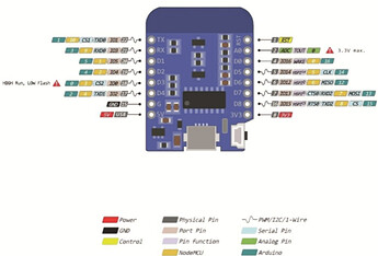
I use a d1mini chip. The pin assignment can be seen in this picture. Especially the Arduino pinout is important. (GPIO) With these numbers I can control the pins using Homeassistant.

Controllerbox

The Controllerbox I use has the pin assignment noted on the back. (see red marking)

So I created this table that shows the used pins with the ethernet-cable connected to the Controllerbox. (I looked at the 10-pole Ethernet cable and saw which pins are not used) Those colors I use everywhere. (on the two adapters, the chip, …)

Sequence in power supply | G     | TX    | RX    | Key2 | Key1 | G      | B-C1 | SWD  | 5V    | DC
--------------------------------------------------------------------------------------------------------
Color                    | brown | black | white | free | red  | purple | free | free | green | yellow

Touchpad

Thats the touchpad I am using. I think that there is nothing special. Unfortunately I don’t have a data sheet or something like this.

Physical Structure

At the moment I have a working bridge with the two adapters (Adapter1: 10-pole Ethernet cable from touchpad to 8-pole Ethernet cable, Adapter2: 8-pole Ethernet cable to 10-pole Ethernet cable from touchpad). So I can still manually raise and lower my table using the touchpad. I also managed to read out the RX output. (I took the G cable and the TX cable of the 8-pole Ethernet cable from Adapter1 and connected it with the corresponding pins of my d1mini).

I guess that it works like on the following image:

  1. TX → Chip; TX → Touchpanel
  2. RX → Controllerbox
  3. TX → Controllerbox
  4. RX → Touchpanel; RX → Chip
  5. … start again

Reading UART-Messages

This is the configuration I use to read out the uart-messages from the rx-pin. (rx cable from the Ethernet cable is connected to the rx-pole of the d1mini chip)

esphome:
  name: esphome-web-755eb2

esp8266:
  board: esp01_1m

# Enable logging
logger:
  baud_rate: 0

# Enable Home Assistant API
api:

ota:

wifi:
  ssid: !secret wifi_ssid
  password: !secret wifi_password

captive_portal:

uart:
  - id: desk_uart
    tx_pin: 1
    rx_pin: 3
    baud_rate: 5600
    debug:
      direction: BOTH
      dummy_receiver: true
      after:
        bytes: 3
      sequence:    
        - lambda: UARTDebug::log_binary(direction, bytes, ',');
        # - lambda: UARTDebug::log_int(direction, bytes, ',');

image

When I press different buttons on the touchpad, I get different values, which I have recorded in this table.

baudrate hexadecimal binary(only the middle byte) meaning
5600 0xFF 0xF0 0x14 0b11110000 idle
5600 0xFF 0xF4 0x14 0b11110100 up
5600 0xFF 0xF8 0x14 0b11111000 down
5600 0xFF 0xB1 0x14 0b10110001 Preset 1
5600 0xFF 0x72 0x14 0b1110010 Preset 3
5600 0xFF 0xD0 0x14 0b11010000 M
5600 0xFF 0x91 0x14 0b10010001 M + Preset 1
5600 0xFF 0x52 0x14 0b1010010 M + Preset 3

At this point I noted, that these value differ when using different baudrates. So I want to stick at 5600 at the moment.

Thoughts and problems

  1. I am not sure, in which order the bytes are sended. Somethimes the output has the same values, but they are in a different order.
  2. I don’t really know for what the Key1 pin is used. For now I just don’t use it at all.
  3. I don’t know how I should connect the rx and tx cables to the pins. I just tested some variations and for now I stick with the described variation, where I get the uart-output. (rx to rx-pin and also in the configuration rx-pin is set to GPIO pin 3)
  4. At the moment I am outputting 3 bytes. I think that at least this should be correct, because the output always repeats after 3 bytes.
  5. I saw in this thread that only the tx pin is used. However, this may be a special case for this Controllerbox I guess.
  6. Like many other Controllerboxes this one does not have a specific up / down cable.

I would love the get some more advices or help for my problem. If I missed some necessary information, let me know that. Thank you!
1 Like

Nice write-up and great progress.

I think Desky may actually use tx but the project doesn’t use it yet. Mainly for the commands for the initial configuration you’d do like height limits and setting presets. No sure though.

You might find reading through Phords protocol notes useful in discovering your own.

You may want to get a logic analyzer if you haven’t got one. These ones are cheap and seem to work fine.

AU $7.46 13%OFF | USB Logic Analyzer 24MHz 8 Channel 24M/seconds Logic Analyzer Debugger For ARM FPGA Logic Analyzer Logic 24M 8CH
https://a.aliexpress.com/_mtgxHGe

Sounds like you still need to do a bit more digging/discovery on your uart messages, but once you’ve figured it out, you could also look at this alternative to reading uart.

Also if you need help decoding uart, Discord is a good place to ask for help. Especially if you can get some of ssieb’s time.

1 Like

9600 seems to be more common. I have no clue about these things though…

1 Like

If you get the wrong baud rate, you’re going to get strange (and probably varying) data results. A logic analyzer is really helpful for figuring that out.

2 Likes

Those tend to be expensive… unless there’s DIY logic analyzer? I don’t know… I’d need one of those too

1 Like

Check the one I linked (which ssieb recommend to me).

2 Likes

I bought this one and tested it immediately.

Here is the result, when I operate the desk manually (The colors do not match the colors of the cable!):

Number-Explanation

Number Key1 G (not the G for TX and RX) 5V Meaning
1 1 0 0 The display on the touchpad is turned on. (when pressing any key)
2 1 1 0 I touched the up-key (↑) of the touchpad and the desk is moving upwards.
3 1 1 1 I touched the down-key (↓) of the touchpad and the desk is moving downwards.

Now I am trying to create this behaviour via Software. (HomeAssistant) I will share my results in this thread.

1 Like

I also can recommend the @Mahko_Mahko mentioned. Their easy to use with the Logic-Software.

2 Likes

You can also look at Sigrok/PulseView for compatible free software.

2 Likes

You may want to look into uart decoding with your analyser. See example on this page.

https://sigrok.org/wiki/Getting_started_with_a_logic_analyzer

2 Likes

I decoded the messages again, but this time with a baudrate of 9600:

baudrate hex-values meaning
9600 0xA5 0x00 0x00 0xFF 0xFF idle
9600 0xA5 0x00 0x20 0xDF 0xFF up
9600 0xA5 0x00 0x40 0xBF 0xFF down
9600 0xA5 0x00 0x02 0xFD 0xFF Preset 1
9600 0xA5 0x00 0x04 0xFB 0xFF Preset 2
9600 0xA5 0x00 0x08 0xF7 0xFF Preset 3
9600 0xA5 0x00 0x01 0xFE 0xFF M

This values seem to be more accurate and precise than using a baudrate of 5600.
I checked the values with the already mentioned Logic Software and also with the rx-pin on my chip.

1 Like

Nice. They seem to be cleaning up?

Now you could maybe try sending one of them (say a preset), with the UART write?

1 Like

Actually I tried some stuff this weekend and now I can read out the correct height of the desk.
I read out the tx-uart-messages with the logic-analyzer and saw some dependencies in the value. The desk height is between 72.0cm and 119cm. From 72.0 to 99.9cm there is one decimal-digit. From 100 to 119 there only integers.

Mian-Learnings

Tx sends 6 bytes and heres what they mean:

Byte Meaning
1 constant value: 0x5A
2 tens digit of the height
3 units digit of the height
4 1st decimal digit of the height
5 constant value: 0x01
6 propably a kind of an id (actually the sum of all the other bytes divided by a specific number I don’t know) → I measured every value for every height (round about 280) and collected them in another table, which I won’t upload here, as it is too big und for this progression not needed.

Here is an example of the height 75.7:

I compared some values and found out:

Tens

Value Byte
7#.# 0x07
8#.# 0x7F
9#.# 0x6F
1## 0x06

Units

Value Byte
#0.# 0xBF
#1.# 0x86
#2.# 0xDB
#3.# 0xCF
#4.# 0xE6
#5.# 0xED
#6.# 0xFD
#7.# 0x87
#8.# 0xFF
#9.# 0xEF

1st decimal

Value Byte
##.0 0x3F
##.1 0x06
##.2 0x5B
##.3 0x4F
##.4 0x66
##.5 0x6D
##.6 0x7D
##.7 0x07
##.8 0x7F
##.9 0x6F

So I can read out every byte that is send via uart.
For this I wrote my own esphome-custom-component. Here you can find the repository. The currently active branch is feat/desktronic. (I had some inspiration from @ssieb here) Here I will just mention the important part of the component:

Main-Loop for getting the current-height

void Desktronic::loop()
{
    static int bytePositionInUARTMessage = 0;
    static double height = 0.0;
    bool beginning_skipping_garbage_bytes = true;

    while (esphome::uart::UARTDevice::available())
    {
        uint8_t byte;
        esphome::uart::UARTDevice::read_byte(&byte);

        // the uart-messages just get read. So they also can start in the middle of a message
        // in this case, these "garbage-bytes" have to be skipped
        if (beginning_skipping_garbage_bytes)
        {
            if (is_skipping_garbage_byte(byte))
            {
                continue;
            }
            else
            {
                beginning_skipping_garbage_bytes = false;
                bytePositionInUARTMessage = 0;
                height = 0.0;
            }
        }

        handle_byte(byte, bytePositionInUARTMessage, height);
    }
}

Managing how the bytes of the uart-message is parsed to a valid height.

void Desktronic::handle_byte(const uint8_t byte, int& bytePosition, double& height)
{
    switch (bytePosition)
    {
    case 0: // everytime 0x5A
        bytePosition = 1;
        break;
    case 1:
        // 70, 80, 90, 100
        height += get_tens_digit(byte);
        bytePosition = 2;
        break;
    case 2:
        // 0, 1, 2, 3, 4, 5, 6, 7, 8, 9
        height += get_units_digit(byte);
        bytePosition = 3;
        break;
    case 3:
        // 0, 0.1, 0.2, 0.3, 0.4, 0.5, 0.6, 0.7, 0.8, 0.9
        height += get_first_decimal_digit(byte);
        bytePosition = 4;
        break;
    case 4: // everytime 0x01
        bytePosition = 5;
        break;
    case 5: // the uart-message is complete
        current_pos_ = height;

        // update the height-sensor
        if (height_sensor_)
        {
            // accuracy is set in __init__.py
            height_sensor_->publish_state(height);
        }

        // reset the height and position
        bytePosition = 0;
        height = 0.0;

        break;
    default:
        break;
    }
}

I unfortunately had to do this with those static-variables because of the problematic of the garbage_bytes at the beginning. Because of this I cannot read out 6 bytes at once.

My Yaml-File looks like this:

...

################################################
# Ready for production (this should word as expected)
################################################

external_components:
  - source:
      type: git
      url: https://github.com/MhouneyLH/esphome_custom_components
      # ref: feat/desktronic
      # ref: feat/test
      ref: feat/old_test
      # ref: feat/without_map
    refresh: 10s
    components: [ desktronic ]

uart:
  - id: desk_uart
    rx_pin: 1
    baud_rate: 9600

desktronic:
  id: my_desktronic
  height:
    name: DeskHeight
  up:
    number: 14
  down:
    number: 12
  request:
    number: 4
  stopping_distance: 0
  timeout: 5s

Thats the result for now that makes me pretty happy for now :slight_smile: (its on less fps; on my pc it is realtime to the moving-desk):
height_sensor

Problems

I came across 2 problems:

  1. The flash-size is of my esp8266 is not enough to story the current program + the generated copy of it as I already use round about 65% of the space. So I have to clear out the whole esp in order to have the newest software on the device. I guess the easiert solution for that is to buy another esp with more flash-size.
  2. Sometimes I have problems to be connected to the esp. (When I am installing the new software on the device) The error message after waiting about 30secs:

    After that message it automatically connects. Maybe somebody had to deal with something like this in the past and know what to do about it.

Next Step

Now where I have this working state I am trying to move the desk via software.

1 Like

Great progress!

I would get an esp32 for sure.

Sounds like byte 6 is a checksum.

You can try using a static IP in improve connection time.

1 Like

Esp32 looks quite good. 4 Mb of Flash-Memory and 530 Kb SRAM.

image

I already tried using a static IP. This does not speed up the process for me.

1 Like

You can also look at this thread for recommendations.

Do you have the static IP set both in your router and your esp config?

You can also try fast_connect.

Yes, but unfortunately this also does not work. But thats not a big problem for now.

I had already made a component for this type of desk. The height bytes are actually the 7-segment display output values. If you put an ESP32 between the display and the desk, my component can read the height value and the buttons you press. I’m currently working on adding the capability for moving the desk.

external_components:
  - source:
      type: git
      url: https://github.com/ssieb/custom_components
      ref: jsdrive
    components: [ jsdrive ]
2 Likes

Wow, im currently on the same state. Then I will try to work with your code and try to figure out how to move the desk by software.