Wifi Night Light with Motion - Globe 50239 - WB3S - LocalTuya / OpenBeken / LibreTuya / ESPHome

Hey all -

Relatively new to posting on here, so bear with me as I fumble my way through it!

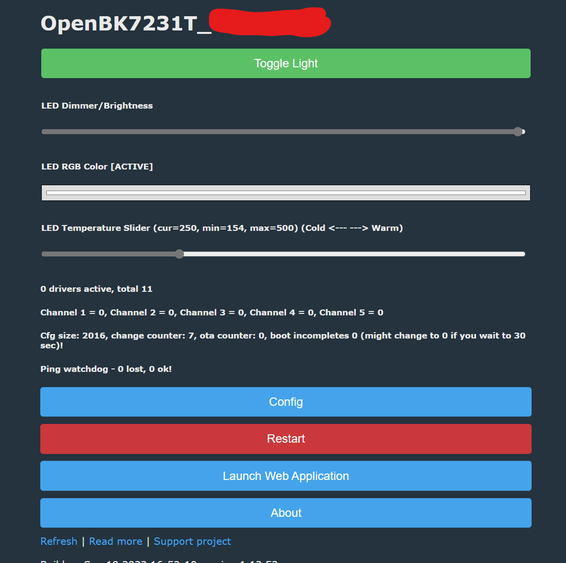
Going to write up a small walkthrough on a relatively niche product - including LocalTuya config, and physical (no soldering!) flashing of it with OpenBeken and LibreTuya ESPHome configuration.

Quick Intro
I was looking for a mains-powered (no batteries!) “nightlight” which could be linked together (e.g., multiple turn on in sync down a hallway). For some reason, this seemed like a major gap in the market. Eventually I found a plug-in “Smart Ambient Light” which is produced by Globe Electronics, and compatible with Tuya. Thus began my adventure, starting with using them on LocalTuya, and then actually cracking them open to flash my own firmware.

First post will be about the hardware itself…

Globe 50239
“Smart Ambient Light”
Amazon Product Listing
Manufacturer Website

MSRP: ~$30USD
Availability: picked it up for $12 per on Ebay, current Amazon list was $20

Description: Simple plug-in RGBWW LED and Motion sensor - Wifi connection using Globe app (Tuya re-brand).

Chip: WB3S controller


LocalTuya Config
The device is compatible with LocalTuya and exposes a number of controls. Downside of this is that many of the control options are linked together and makes creating the configuration a pain.

Disclaimer - not 100% confident in the use of some of the entities in the configuration.

Pros:

  • No messing with the hardware
  • Semi-local control
  • Keeps it all “stock”

Cons:

  • Creating the entities in the LocalTuya UI is a real pain (LMK if I am missing some trick to simplify this.)
  • No ability to separate the trigger of the motion sensor with the toggle of the light (e.g., I want to use the motion sensor to trigger overhead lights at some hours, only trigger the “night light” LEDs otherwise).
  • Still Tuya :slight_smile: and where’s the fun in that?

Configured Entities:

9 controls + 1 Sensor

The config I used:

  • Light (DP 20) - Main light controls
    • Brightness=22
    • ColorTemp=23
    • Lower=10
    • Upper=1000
    • ColorMode=21
    • Color=24
  • Number (DP 26) - “Countdown(Note: not sure what this does)
    • Lower=0
    • Upper=86400
  • Binary Sensor (DP 52) - “Motion Sensor
    • On=pir
    • Off=none
    • Class=motion
  • Select (DP 51) - “Device Modeauto = PIR on, responding to motion
    • Entities=auto;manual
  • Switch (DP 56) - “PIR SwitchTurns PIR sensor on/off
  • Select (DP 54) - “PIR Sensitivity(Note: does not appear to be changeable via API)
    • Entities=low;middle;high
  • Number (DP 55) - “PIR Delay(Note: not sure what this does)
    • Lower=5
    • Upper=86400
  • Number (DP 58) - “Standby TimeHow long in minutes does the light stay on after trigger (tied to DP 59)
    • Lower=1
    • Upper=480
  • Number (DP 59) - “Standby BrightnessWhat brightness after the trigger (for Standby Time duration)
    • Lower=0
    • Upper=1000
  • Select (DP 53) - “CDS(Note: not sure what this does)
    • Entities=2000lux;300lux;50lux;10lux;5lux;now

The issues:

  • Changing the light using the UI/Automation automatically changes “Device Mode” to “Manual”. This means that I had to have the automation automatically change to “Auto” after changing the light. But…
  • Changing the “Device Mode” to “Auto” resets the PIR sensor to clear, and turns off the light. So I added a delay between changing the light, then changing device mode
  • PIR Switch seems to effectively do the same as changing from “Auto” to “Manual”
  • PIR Sensitivity seems not to do anything
  • No idea what “CDS is” but changing it to anything but “2000lux” seems to break all other capabilities

Flashing OpenBeken / LibreTuya

First off, usual disclaimers - you’re playing with a mains-voltage device, don’t be stupid, unplug before you disassemble, don’t touch things. Be careful and I am not responsible for you getting hurt.

This device wasn’t particularly easy to get open - need to pry apart the pieces which appear to have been bonded together. This means putting it back (it did snap back in) might not be as strong as before.

This post I’ll get into how I cracked the device open, dumped the firmware, and loaded alternatives.

Much thanks to the guys who made OpenBeken and LibreTuya! Not long ago this wouldn’t have been possible.

Step 1: Cracking it open…
No easy way, I used a metal scraping tool to pry open on one edge, just used gentle pressure and patience. Then I used a phillips driver to undo the single screw holding the board in the plastic case.

Step 2: Checking out the hardware…


Hardware:

Step 3: Connecting it up!
I used a USB to TTL adapter to connect to the pins on the WB3S chip directly. I printed a small flashing jig to make this easier and more repeatable. By connecting the “CEN” pin to the RTS header on my usb adapter, I didn’t need to manually reset the device into programming mode. If you do not have that header, then you can touch CEN to GND when you are flashing.


Step 4: Flashing OpenBeken
If you aren’t familiar with the OpenBeken project, it’s a Tasmota-esque firmware for Beken-based devices. The github is here; many projects documented here.

I’ve found that the BK_writer app is not usable or stable. On two different devices now, it was capable of reading from the chip, but not writing out.

I used the python UART program here.

Step 5: Connect OpenBeken
Once flashed, reset the device. This should then create a local wifi AP that you can join. This process is very reminiscent of Tasmota :slight_smile:

Step 6: Configure OpenBeken
Took a bit of trial and error, but I was able to identify the correct pins that you can setup in the configuration.

  • Light PWMs…
    • Pin 6 = Warm White (channel 5)
    • Pin 8 = Cold White (channel 4)
    • Pin 9 = Red (channel 1)
    • Pin 24 = Green (channel 2)
    • Pin 26 = Blue (channel 3)
  • Button
    • Pin 1
  • PIR
    • Pin 14

LibreTuya ESPHome Config

LibreTuya has a fork of ESPHome which works with non-ESP devices. Setting it up on my computer to compile was a bit of a pain, and OTAs don’t seem to be working, but I was able to create a pretty solid configuration readily.

esphome:
  name: nightlight

libretuya:
  board: wb3s
  framework:
    version: latest

# Enable logging
logger:

# Enable Home Assistant API
api:
  password: XXXXXXX

ota:
  password: XXXXXXX

wifi:
  ssid: XXXXXXX
  password: XXXXXXX

  # Enable fallback hotspot in case wifi connection fails
  ap:
    ssid: "Fallback Hotspot"
    password: XXXXXXX


#captive_portal:

web_server:
  port: 80

light:
  - platform: rgbww
    name: "Night Light"
    red: output_component1
    green: output_component2
    blue: output_component3
    cold_white: output_component4
    warm_white: output_component5
    cold_white_color_temperature: 6536 K
    warm_white_color_temperature: 2000 K
    color_interlock: true

binary_sensor:
  - platform: gpio
    pin: D1
    name: "PIR Sensor"
    device_class: motion

  - platform: gpio
    pin: 
      number: D7
      inverted: true
    name: "Button"

output:
  # Red
  - platform: ledc
    id: output_component1
    pin: D8

  # Green
  - platform: ledc
    id: output_component2
    pin: D3
    
  # Blue
  - platform: ledc
    id: output_component3
    pin: D2

  # Cold
  - platform: ledc
    id: output_component4
    pin: D9
    
  # Warm
  - platform: ledc
    id: output_component5
    pin: D4

4 Likes

Hello and welcome!!!

Thank you for this write up, very helpful!!!

I have some other Tuya chip based devices, mainly lights, that I have wanted to get totally local control of. I knew folks were working on reversing the Tuya chips and reading your experience showed me how far folks have gotten. I bought one of the night light devices that you wrote about and followed your steps. Very easy to do. I’ve only gone as far as using OpenBeken to get comfortable with the reliability.

I have a couple questions if I may…

  1. Could your tell me about your pogo pin rig. Is it a 3-D print or something you purchased?

  2. Do you have a sense for what is the best path? OpenBeken, the ESPHome fork or the raw LibreTuya PlatformIO Arduino route… Each seems to have pluses and minuses. And which will see the most robust improvements.

  3. Did you have to use the physical UART connection to move from OpenBeken to the ESPHome fork? Or is OTA between the two currently possible?

Again thanks for your guide, this work really opens up some nice home automation products to being able to be ‘off the cloud’ and completely local.

Big thanks for that extra tip on connecting CEN to RTS. Wasn’t aware there was another method other than grounding CEN pin or power cycling it.

How were you able to test the pin for PIR sensor?

  1. Yes, OTA is doable.
    On Openbk, you’ll need to to rename libretuya .rbl firmware to OpenBK7231T.rbl or OpenBK7321N.rbl depending on your device.

On libretuya, convert the openbk.rbl firmware to .uf2 using lchiptool, then upload to your web server. Example:

#convert rbl to uf2
ltchiptool uf2 write -f bk7231n -b generic-bk7231n-qfn32-tuya -o openbkt.uf2 download;OpenBK7231N_1.12.50.rbl
2 Likes

Thank you for the info on OTA moves!

I have the PIR and Button on the unit configured ‘dinput’ at P1 / 6 and P14 / 7. I find the Button is inverted, but I just left it. The PIR is really not much to talk about, seems pretty limited but it does work. Under the Openbk path, a simple MQTT test of using a bash script and mosquitto_xxx utilities:

#!/bin/bash
echo "Bash version ${BASH_VERSION}..."

while :
do

    PRI=$(mosquitto_sub -C 1 -h 192.168.2.242 -t nightlight_01/7/get)
    echo $PRI

    if [[ $PRI -eq 1 ]]
    then
        mosquitto_pub  -h 192.168.2.242 -t 'nightlight_01/2/set' -m "99"
    else
        mosquitto_pub  -h 192.168.2.242 -t 'nightlight_01/2/set' -m "0"
    fi

done


As for the flashing jig, I used this: Bin Flashing Jig for Tuya - tywe3 with 16mm pogo pins by FFranzmann - Thingiverse

Personally, I ended up staying on the ESPHome fork for now, just because of my familiarity with the YAML model. I’m hoping it might one day be merged into the main version.

1 Like

Thank you for the jig info, I will now track down the right pogo pins.

I’m going to explore each of the software stacks and see were I go.

If I could ask one more q. What USB / UART device are you using with the RTS to CEN reset and how does this work? Some of the Tuya modules I have tried, if I set CEN to GND, I get a short that resets the UART. CE does not seem any better. So far I my best path is I just toggle the power to the Tuya board to get in right mode to flash.

Also I have found that the USB / UART devices I have do not provide enough power for some of the Tuya boards for flashing, I have ended up powering the Tuya boards with a breadboard simple power supply and just using the USB / UART for the 3.3 v level tx/rx. If you can show me how to get the python flashing program to toggle some kind of reset at beginning, this seems cleaner.

Thanks again!

On the OTA swap, can you elaborate a bit more?

On the OpenBeken → ESPHome (port)…

  • wrote the ESPHome config
  • compiled config on local, using libretuya-esphome
  • looking at the “libretuya-esphome\.esphome\build\{devicename}\.pioenvs” folder

which file there needs to be renamed to “OpenBK7231T.rbl”?

I see a few contenders:

  • “bk7231t_app.ota.rbl”
  • “bk7231t_app_0x011000.rbl”
  • “firmware.uf2”
    ???

It’s ota rbl file, the first one

First of all, thank you mattjacobson6. This write up was super helpful and I was able to make all the way to the openbeken install. Plugged the nightlight in and it works. I decided to try LibreTuya ESPHome fork but i’m running through some issues.

Following the guide in ESPHome port - LibreTuya, I’m able to use the wizard to create the yml file. I modified the yml with the one you shared. When I run the command to compile (python -m esphome compile yourdevice.yml), I get some errors:

I have tried running the compile command a few times and it seems that I get the same errors for different compiles.

Does anybody have any idea on how to tackle this issue? Any pointers would be appreciated.

Thanks!

Can you share your config?
Some components are not supported yet (eg http_request) will result in error.

Do you mean the yml file? It’s similar to the example above.

esphome:
  name: nightlight

libretuya:
  board: wb3s
  framework:
    version: latest

# Enable logging
logger:

# Enable Home Assistant API
api:
  password: ""

ota:
  password: ""

wifi:
  ssid: "XXXXXXXXX"
  password: "XXXXXXXXX"

  # Enable fallback hotspot in case wifi connection fails
  ap:
    ssid: "Fallback Hotspot"
    password: "XXXXXXXXX"

web_server:
  port: 80

light:
  - platform: rgbww
    name: "Night Light"
    red: output_component1
    green: output_component2
    blue: output_component3
    cold_white: output_component4
    warm_white: output_component5
    cold_white_color_temperature: 6536 K
    warm_white_color_temperature: 2000 K
    color_interlock: true

binary_sensor:
  - platform: gpio
    pin: D1
    name: "PIR Sensor"
    device_class: motion

  - platform: gpio
    pin: 
      number: D7
      inverted: true
    name: "Button"

output:
  # Red
  - platform: ledc
    id: output_component1
    pin: D8

  # Green
  - platform: ledc
    id: output_component2
    pin: D3
    
  # Blue
  - platform: ledc
    id: output_component3
    pin: D2

  # Cold
  - platform: ledc
    id: output_component4
    pin: D9
    
  # Warm
  - platform: ledc
    id: output_component5
    pin: D4

Compiled just fine for me,
Looks like someone had the same issue, try updating libretuya

Hmm, I tried using the ota rbl but rejected by the openbk ota interface (drag and drop). Am replying now many months later but do you have any suggestions?

Edit:

Added version to name and now OK. Please ignore :slight_smile:

Make sure to rename it based on your device chip
If it’s bk7231t, then it’s openbk7231T.rbl

Thanks for the awesome write-up!

I purchased one on Ebay for $14. Because of @mattjacobson6 's hard work, the hardest part of the process was breaking through all the glue. An iFixit “jimmy” tool did the trick with about 20 minutes of prying.

For anyone else doing this this, just take your time prying the translucent cover off. I let the pry tool go a little too far in and put some gnarly scratches on the PCB. Luckily the scrapes are contained to the ground plane, so no real harm done.

First I flashed OpenBeken, but got lazy when I learned it required MQTT. So, I OTA flashed to the libretuya-esphome fork. As @Michael_Lowe said, bk7231t_app.ota.rbl needs to be renamed to include a version number. Once I renamed it to OpenBK7231T_1.15.393.rbl, it worked flawlessly.

In the future, I’m thinking about replacing the WB3S with an ESP32 to use a vanilla ESPHome and use the light as a bluetooth proxy.

I am getting a timeout error even though I have it all hooked up correctly and compiled the yaml. Does this mean anything to anyone to see where I am going wrong?

C:\Users\xxxx\libretuya-esphome>python -m esphome upload nightlight.yml
INFO Reading configuration nightlight.yml...
Found multiple options, please choose one:
  [1] COM12 (Silicon Labs CP210x USB to UART Bridge (COM12))
  [2] COM5 (USB Serial Device (COM5))
  [3] Over The Air (hallway-nightlight.local)
(number): 1
************************************************************************************************************************
Obsolete PIO Core v6.1.5 is used (previous was 6.1.6)
Please remove multiple PIO Cores from a system:
https://docs.platformio.org/en/latest/core/installation/troubleshooting.html
************************************************************************************************************************
Processing hallway-nightlight (board: wb3s; framework: arduino; platform: libretuya)
------------------------------------------------------------------------------------------------------------------------
Verbose mode can be enabled via `-v, --verbose` option
Warning! Non-Git installations are NOT SUPPORTED.
CONFIGURATION: https://docs.platformio.org/page/boards/libretuya/wb3s.html
PLATFORM: LibreTuya (0.12.6) > WB3S Wi-Fi Module
HARDWARE: BK7231T 120MHz, 256KB RAM, 1.03MB Flash
DEBUG: Current (openocd) External (custom, openocd)
PACKAGES:
 - framework-arduino-api @ 3.0.0-a4cbfc+sha.3a4cbfc
 - framework-beken-bdk @ 0.0.0+v2021.06.07.sha.6491b8c
 - library-flashdb@03500fa @ 3500.0.0-fa+sha.03500fa
 - [email protected] @ 2.1.3-bdk+sha.33191e0
 - [email protected] @ 6.0.0+sha.8b831c1
 - tool-ltchiptool @ 2.0.2+sha.7559033
 - tool-openocd @ 2.1100.211028 (11.0)
 - toolchain-gccarmnoneeabi @ 1.40804.0 (4.8.4)
LDF: Library Dependency Finder -> https://bit.ly/configure-pio-ldf
LDF Modes: Finder ~ off, Compatibility ~ soft
Found 5 compatible libraries
Scanning dependencies...
Dependency Graph
|-- ESPAsyncWebServer-esphome @ 3.0.0
|   |-- AsyncTCP-esphome @ 2.0.0
|-- noise-c @ 0.1.4
|   |-- libsodium @ 1.10018.1
|-- ArduinoJson @ 6.18.5
Building in release mode
Building UF2 OTA image
Checking size .pioenvs\hallway-nightlight\firmware.elf
|-- firmware.uf2
Advanced Memory Usage is available via "PlatformIO Home > Project Inspect"
RAM:   [====      ]  44.1% (used 115628 bytes from 262144 bytes)
Flash: [=======   ]  65.7% (used 712024 bytes from 1083136 bytes)
Configuring upload protocol...
AVAILABLE: uart
CURRENT: upload_protocol = uart
Looking for upload port...
Using manually specified: COM12
Uploading firmware.uf2
|-- Detected file type: UF2 - esphome 2023.1.0-dev
|-- Connecting to 'Beken 7231U/7231T' on COM12 @ 115200
|-- Connect UART1 of the BK7231 to the USB-TTL adapter:
|
|       --------+        +------------------------
|            PC |        | BK7231
|       --------+        +------------------------
|            RX | ------ | TX1 (GPIO11 / P11)
|            TX | ------ | RX1 (GPIO10 / P10)
|           RTS | ------ | CEN (or RST, optional)
|               |        |
|           GND | ------ | GND
|       --------+        +------------------------
|
|-- Make sure to use a good 3.3V power supply, otherwise the adapter might
|-- lose power during chip reset. Usually, the adapter's power regulator
|-- is not enough and an external power supply is needed (like AMS1117).
|
|-- If you didn't connect RTS to CEN, after running the command you have
|-- around 20 seconds to reset the chip manually. In order to do that,
|-- you need to bridge CEN to GND with a wire.
|-- TimeoutError: Timeout while linking with the chip
|   |-- File "C:\Users\xxxxx\AppData\Roaming\Python\Python310\site-packages\ltchiptool\commands\flash\_utils.py", line 33, in flash_link_interactive
*** [upload] Error 1
============================================= [FAILED] Took 35.15 seconds =============================================

I am running everything through the command prompt on windows