PLC Programming

LIGHTING | IRRIGATION | INPUT | TREATMENT | FILTRATION | SOLIDS

AQUAPONIC | [PLC] | SCREENS | SONOFF | myHome-Assistant Project

I would like to pass on some assorted PLC related information for those who may be interested in looking at how PLC’s may be used in your automations.

I would first like to repeat what I mentioned earlier in my introduction to my project.
“The one key feature for me is that: PLC’s operate autonomously with a high degree or reliability and accuracy.”

Given this ability to use all the logic you have built in to your program, the PLC can then continue to function safely while many other systems may fail for various reasons (HA server, Router, MQTT server, Node-Red server, etc) around the PLC system. Due to the PLC system being wired and programmed as a discrete system it will remain working as long as it has (in my case) 24VDC control power for the PLC and 240VAC to run any connected/controlled devices.

In a system where you are looking for 100% reliability this is a must have characteristic.

xLogic Soft

First I would like to give a brief look at the programming software I use. xLogic Soft is a free download and once installed and open on your desktop it looks like the below screenshot. You don’t need to own any PLC’s to start having a go at designing a new program. It is specific to Reivetech PLC’s so if you like another brand of PLC you will need to checkout it’s related software.

In the above image you can see I have a project open called Master PLC 54 (Top Left) and that I am looking at a “Simulation” of the actual PLC (at the bottom of the image) which is displayed powered up with a program status message on the LCD screen telling the user the name of the PLC, which Slot number the PLC is and that it is in the RUN state with No Faults. Note that the PLC used in this program also has 5x expansion modules connected which increases the available Inputs and Outputs substantially.

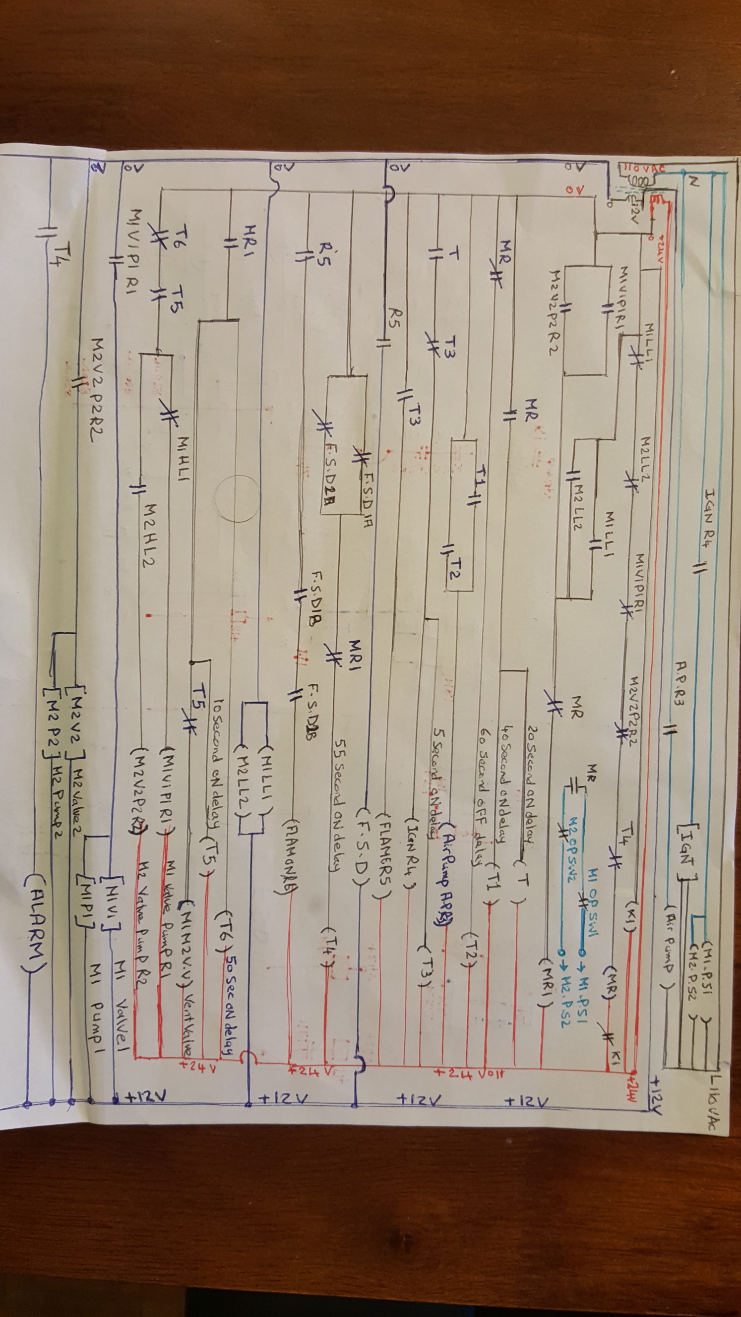
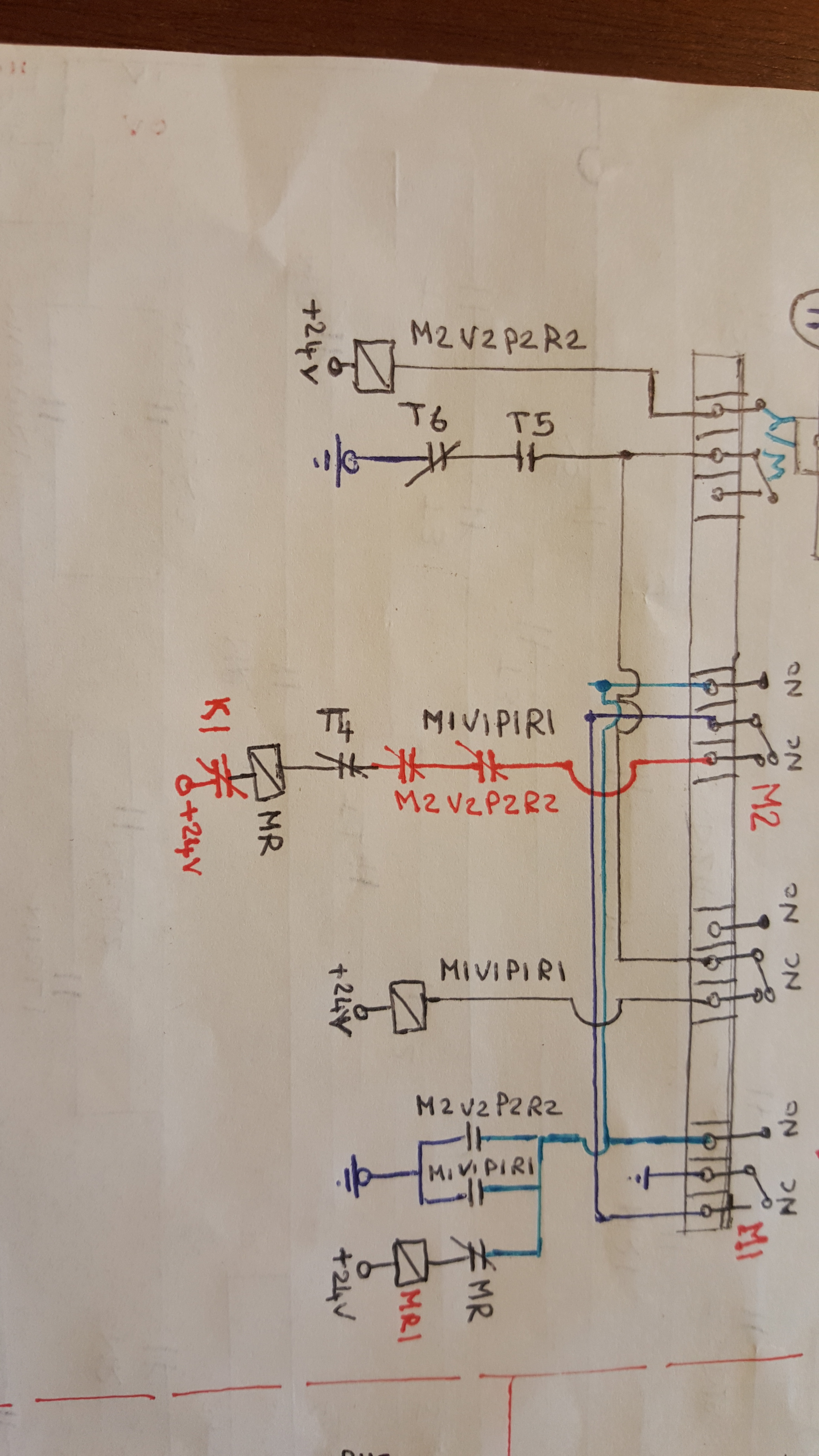
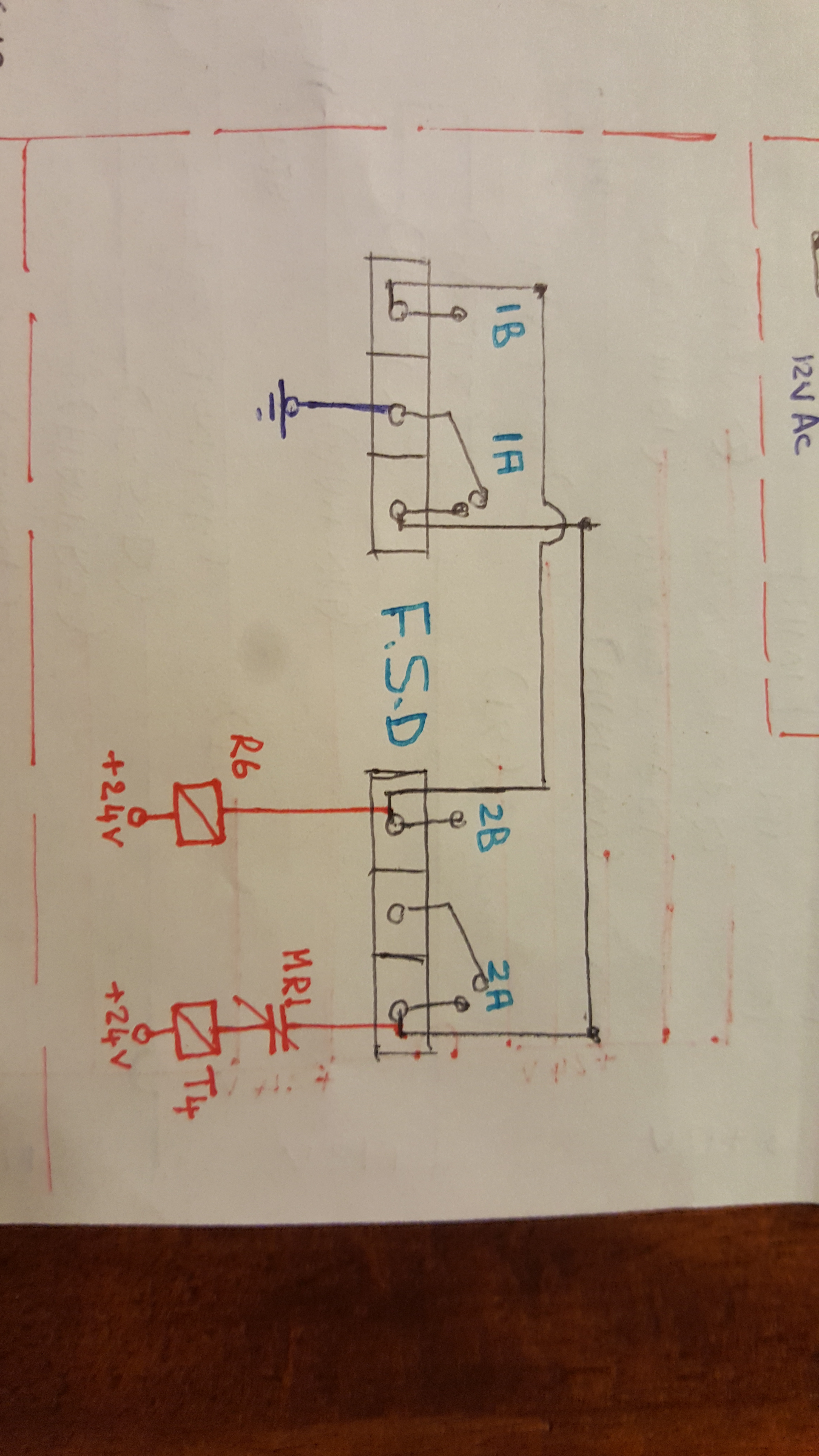
Below is a two page chunk of the complete program which shows the relatively simple Storm Water Sump Pump control system.

The whole program (Master PLC 54) runs to 68 pages (1267 KB) presently. This PLC has had quite a bit of development on it since it came online around 2011 and I only rename at major updates.

If you look closer at the Function Blocks on the page (see above Page 1 of Storm Water Control) you may be able to see one of the features which make this program quite useful when connecting up your sensors, binary sensors, switches, etc, in Home assistant. If you look closely at the F21 Digital Flag labeled as ‘Auto Empty Start’ then to the lower left there is a listing which reads Modbus_0x=1556(614H). The important information to connect that to HA is ‘1556’ which is the coil number. This PLC is Slot 3 (as shown on the LCD screen above) and is Static IP

HA Integration (the short story)

With those two pieces of information I can setup this ‘Flag’ in HA as a modbus switch in my config.
The IP address is also required to setup the Modbus Hub but that is beyond the scope of this discussion for now.

      - name: Storm Water Auto Empty
        hub: hub3
        slave: 3
        coil: 1556

Easy as that!
You can add a bunch of items or one at a time to the HA config but HA must be restarted to bring the new device/devices online and then you will simply need to add your new ‘entity’ to your Lovelace UI.

Function Block Diagrams (or ‘Blocks’)

This software is based on the user picking up ‘Blocks’ from the ‘Workspace’ and dragging them to where you want to place them on the ‘Circuit Diagram’. You then begin wiring up the connections to other ‘Blocks’ until you build a working program.

As a sparky who is used to working with electrical schematics this software came easily to me but I also had to develop more skills with logic boxes of Boolean algebra. Anyone used to that will find it even easier.

The key thing which makes the whole process of creating your programs easy (fun even) is that at any moment you can choose to ‘simulate’ your program which will power up the simulated PLC and give you a chance to see whats working, OR NOT?

Even better, once the program is uploaded to the PLC the software can be connected to monitor the running program live to the PC. When problems need to be diagnosed this feature is priceless as you can scroll around the program you have constructed and read the actual process values. Even the buttons on the PLC can be operated as if you were in front of the PLC.

PLC Expansions & Remote I/O

Most of the Ethernet PLC’S I am using are equipped with 14 inputs (digital and analog) and 8 Relay outputs (8x10amp). Three out of the four areas they cover required substantially more I/O so the answer was to purchase expansion modules. There was a large area within each area with devices clustered in a few areas within the area.

After a lot of research and questions back and forth to my local supplier I came up with a way to extend the distance between expansion modules using a custom made expansion module to ethernet adaptor.

ABOVE: PLC + Expansion 1

ABOVE: Expansions 2 & 3

With this solution I have been able to link expansions which are up to 20 metres separated with no detectable problems arising in PLC performance.
This solution has quite a number of uses for home automation as with one PLC you can have an expansion device (read relay board) with 8x inputs and 8x outputs spaced out across your entire house. This can lead to quite large savings in wiring costs.

More coming shortly…!

myHome-Assistant Project

5 Likes

FYI, when using a Siemens S7 PLC you can write and read I/O’s, even without any actual program written in the PLC.

This can be done by using Node-RED and package (palette):

Be aware, you have to grant ‘PLC remote access’ as described at:
https://github.com/Hilscher/node-red-contrib-s7comm/blob/c1ac115170c497f5fbb7599584445698f2480c4b/USAGE.md#-further-information.

Just another suggestion… :wink:

2 Likes

@Domoticon sounds cool…I’ll have a look and get back to you on that one.

Cheers!

1 Like

I tried it a year ago or so, it was working. Maybe a bigger problem is the Siemens Software, it’s quite expensive (it 's requiring software keys for the programming software, to remove the nag-screen).

There are relative cheap starter kits available in the market, which include a S7-1200 with programming software (TIA portal). I used the software which I used for my work.

EDIT: Link starter kits: https://w3.siemens.com/mcms/programmable-logic-controller/en/basic-controller/s7-1200/starterkits/Pages/default.aspx?tabcardname=starter%20kit%20overview

Because of the use of Node-RED you can do everything you wish for, for example I controlled the PLC, and got messages, using a Telegram-bot, just for fun…

1 Like

Yes the major players in PLC’s have their bread very nicely buttered…look at the other options out there in the market for Mini PLC’s and you may be pleasantly surprised with their affordability, features and quality.

In my profession we sometimes used Unitronics PLC’s for small setups. The software is free and have a lot of pre-configured programming building blocks. The Samba series even have (colored) HMI capabilities build in and are very affordable.

Just a suggestion I want to mention…

1 Like

Couldn’t agree more with your core comments. PLC’s are robust and by executing the core logic inside the PLC and allow ‘remote’ control using an other protocol (modbus in your example) you get the best of both worlds: robustness/reliability of the PLC and capabilities of home automation software like home-assistant.

I have a similar setup but managed to get MQTT pub/sub working on my PLC (QOS 2!). I’m running CodeSys 3.5 which is a runtime that able to run on multiple PLC devices (Wago/Siemens…).

Some examples: using a pushbutton FB the code emit and MQTT event for a single,double and long push. Events are also emitted for changes on a digital output and there’s a FB that acts a digital sensor as well!

I made everything open source: https://github.com/MichielVanwelsenaere/HomeAutomation.CoDeSys3
There’s extensive documentation with examples for integrating the MQTT capabilities in Home Assistant. I’m planning to add more features in the future.

PS: took me quite some time to get everything to work smoothly and well documented, a star on the git repo is most certainly appreciated :wink:

1 Like

I have had a MQTT PLC here for 6 months or so for appraisal/testing purposes but unfortunately the MQTT capability was in fact very limited.

I have had a very brief look at your info and will get back to try to digest it better. I’ll get back to you then.

Cheers!

If possible, could you elaborate on the “good pratices” of wiring a newtork using PLCs & expansion devices ?

My current understanding is that one would only have to run a main alimentation line, and somehow split & distribute the power in a relay box. Thus, no need to run two separate lines for the garage door and the garage light, use a single one and let the PLC (or extension) handle the distribution.

Am I correct to assume so ?

1 Like

I will answer this in full soon with another topic…will need a little time though but I will let you know when posted.

1 Like

Hi Steve,
I admire your hard work and learning process and would like some guidance from you as I am starting to learn how to apply electrical line diagram into a PLC program. I purchased a reivtech wifi PLC EXM12DART…And I read the user manual which covers the product features but still did not find a programming tutorial that explains how to code a simple inputs of switches connected to the PLC internal relays and timers to trigger outputs such as indication lights. My challenge mainly focus on how can i select such virtual relays & Timers and use their NO NC contacts in the same way as if they physically exist
I do have a line diagram that I wanted to implement in this PLC. Also I downloaded the emsconfig and softlogic software where I can drag inputs and timers but no relays and still no explanation for their auxillary NO NC contacts
Your feedback is highly appreciated

1 Like

@Adao I think I can help you with that but if you could please first post at least a part of your line diagram and I will have a go for you. You are right that there is only a limited amount of programming tutorials in the Reivetech literature. There are however a few examples of use for you to look at which talk about different scenarios and show how to wire them and set them up in the software.

They are found in Section 9 of their user manual which can be found here.

That may help you a little for now but please post some of your line diagram here if you could.

PS: Just to confirm that you have the EXM-12DC-DA-RT-WIFI model as they also have 4G WIFI and GSM WIFI models.

Cheers!


Hi Steve,
I appreciate your prompted response, I will post the first page o)f my electric schematics…I just wanted to highlight that my expectations is to assign and use the internal relays And timers which will replace most of the physical one that is used for local control except the one that triggers the physical outputs such as pump valves IGN blower…Etc
The inputs in this page are
K1 thermostat
Two level boards with 4 relays monitoring 4 liquid levels M1LL1 and M1HL1 low and high level M2LL2 and M2HL2
Photocell detection board FSD with two output relays FSD1A FSD2A and FSD2A FSD2B
The PLC Relay outputs will be
MR
APR3
IGNR4
M1V1 M1P1
M2V2 M2P2

If you have any questions please let me know as I sincerely appreciate your assistance and program inputs! of this circuit
Cheers

Hi Steve,
I wish to clarify that I have two voltage supply connected to my rails are +24 & +12 Vdc as the supply diffee to some components.
Also I l wanted to clarify that the level control wiring and it’s output connections that will be considered as inputs to the PLC internal relays and timers can be seen as follows

@Adao Cheers for posting the two drawings! Could you please clarify for me which PLC you have?

The EXM-12DC-DA-RT-WIFI is equipped with 8 inputs (4 X digital/analog and 4 X digital). It is also equipped with 4 outputs (2 X 10A relay plus 2 X 0.3A transistor) so I am a little concerned when you mention:

Of course you can add an expansion device to get more outputs (and inputs) if that is what you are planning?

How are you planning to utilise the inputs on the PLC?

You said:

How are you going to utilise these as PLC inputs/outputs when they are built in to an existing control device?

Are you planning to supply your PLC with 24V or 12V?

The 2 X relay outputs are ‘dry’ contacts so you can switch either 12 or 24 V easily but the transistor outputs are severely limited in switching capability so you need to consider that.

The drawings you have provided look like they are schematics for a Gas Water Heater possibly?
I am not sure you really should be looking at modifying a device of that nature? There may be safety and legal ramifications if you do?

For now I will await further advice from you regarding the above questions.

Hi Steve,
First, The PLC is EXM-12DC-DA-RT-WIFI with an expansion module that will cover all inputs and outputs
Second, I appreciate your sincere advise as I am not altering nor breaching any safety of an existing device
Third, the PLC will be powered by +24 Vdc and the inputs from the two external control units liquid and photocell will be considered as on off switches connected from the 0V common rail as I will include the photocell board connections as well for your reference
Kind regards

Fair enough…as long as you do understand that altering or overriding Gas Heating Control is a big thing. I trust you keep that in mind as you move forward.

I am sorry, but to be honest all the drawings you have posted leave me still unclear what it is you hope to achieve with the PLC program right now?

So…I just re-read your earliest post and to answer this:

First I would ask: have you had a look at the emsconfig software at all yet and tried starting your first project?

Next I would ask: Do you have any understanding at all with the use of logic gates?

If your answer is no to both then you have quite a bit to learn before we go any further.

As a starting point I would ask that you dive in and open the emsconfig software and once you have it open Click the ‘Help’ Menu and Choose ‘Contents’. (Note I use xLogicSoft in preference to emsconfig…I prefer it for some reason and they both do the same job) Download that from here if you want to compare them.

Scroll around and read about all the Function Blocks available but in particular Have a look at the below items in the ‘Index’ :
Introduction
File → New
Selecting blocks
INPUTS
Outputs
On-delay
Off-delay
Connecting blocks
AND
NAND
NOR
NOT
OR
XOR

In fact go through them all (the ‘Help Files’) at some point because you will find out all you need (well mostly) by getting well aquainted with the software interface.

After you have had a good look at all that and get back to me by a PM and we can discuss this further privately if you like?

If not I’m happy to continue the coversation here if you would rather but I’m tipping there may quite a bit of back and forth between us for a while to get you on your way.

Have Fun and hera from you soon!

Hi Steve,
I appreciate your patience and I have downloaded the eSms config software and I have attempted my first program trial as seen below


It will be very clear that I had no choices to use unnecessary number of DI inorder to replace the dry contacts of the interanal relays and timers to complete the control sequence also I tried my best to label each DI input with reference to its coil
Obviously this is my main struggle let me know how can I assign the logic of a dry contact for either Timer or Releay that can be used in any of the rungs
Also how can I PM …You direct for further assistance
Cheers

@Adao If you would like to PM me just click my Icon and click ‘Message’ I have been trying to message you but after drafting two they seem to be failing atm.

If you include your email address in the PM I will send you fully functional program that may help get you started.

Cheers!

PS: If the two messages arrive please let me know but they don’t show up as being sent here?