LIGHTING | IRRIGATION | INPUT | TREATMENT | FILTRATION | SOLIDS
AQUAPONIC | PLC | SCREENS | SONOFF | myHome-Assistant Project
Sonoff Basic | [Sonoff Mini]
Sonoff Mini - My First Mods
Over the past 12 months I have found a lot of uses for modified Sonoff Basic devices but this is my first attempt to find some more uses for this new sonoff device.
After flashing Tasmota using the ‘solder 4 small leads on method’.
NOTE: Black is GND Red is 3.3V Yellow is TX and White is RX.

I moved on after a period of testing two flashed Mini’s for a while to have a go at setting one up to do a specific job which I have a Wemos D1 Mini doing at the moment. For a few reasons I have not been happy with the wemos performance so I was keen to see what the sonoff Mini could do!
In this project, what I need is to operate 3 lights (via a 4 relay module) and connect two PIR movement sensor modules.
First job was to setup the device to run on 5V power and connect to the available GPIO’s I was planning to use.
Step 1
Red is 5V supply, Black (on S_OUT) is GND supply, Orange is GPIO0, Yellow is GPIO2, Green is GPIO3 (RX) and Blue is GPIO1 (TX)

Step 2
Add Brown wire to connect to 3.3V which will be used to supply 2 X PIR Sensors and then arrange the wires to be brought outside the case for use in the project at hand.
DISCLAIMER: I am not (and never will be) using 240V at all on this sonoff Mini so having these wires pass by the 240V tracks is not an issue.

After that a small section was filed out of the case to allow the wires to pass neatly outside without being pinched as the case was closed up.
PHOTO COMING SOON: sorry but I missed the photo opportunity today.
Then the modified sonoff Mini was setup with the desired GPIO functionality and tested thoroughly with default settings from the Tasmota Flash prior to actually connecting to a 4 channel 5V Relay module and 2 X PIR sensor modules.
To setup the functionality in advance I used the ‘Configure Template’ interface in the sonoff web interface to setup GPIO’s required.

For now all you really need to know is that this is the area where you can setup how you want the GPIO’s to be used for your purposes. It’s also very good for prototyping a new project as you can chop and change as you are designing your new project.
What I’m connecting to.

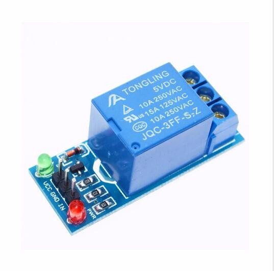
On the relay board note the far right ‘JD’ terminal. Then note the bottom right GND, IN1, IN2, IN3, In4 and VCC terminals. See below for connection details.

Centre: 1.4mm 6 pin female header: GND = Black, IN1 = not connected (Spare), IN2 = Blue GPIO1, IN3 = Yellow (GPIO2), IN4 = Green (GPIO3) and VCC = Red (5V)
Right: I removed the yellow header jumper and connect the 5V to the ‘JD’ terminal.
Then when I open the ‘Main Menu’ and I see my sonoff Mini has 5 relays.

Relay 1 is the internal Mini Relay or GPIO12 while Relay 2 is GPIO1, Relay 3 is GPIO2, Relay 4 is GPIO3 and Relay 5 is GPIO5.
See Schematic below

Photo of the still prototype physical layout. Next step is to fabricate some PVC panels to improve the mechanical segregation of the 5V and 240V but there is plenty of space between them even though it may not look like that atm.

The sonoff Mini is tucked in behind and to the left end of a sonoff Basic which performs another separate task atm.
As of today this is day 2 of my new prototype period so I have tidied up the spaghetti a little.
But how does this all work?
Relay 1 (the internal sonoff Mini relay) is set to change state when PIR 1 detects movement and then simply going to be detected as a binary (Rumpus Occupied) sensor in HA. I dont actually use that relay for anything other than the MQTT messages it sends. However, it is actually good to hear that relay operate as I walk past to know things are working normally at the outside doorway.
Relay 2 will operate the Tank Pathway Light.
Relay 3 will operate the Patio Area Light
Relay 4 will operate Side Path 1 Light
Relay 5 is set to change state when PIR 2 detects movement on the Patio and then simply going to be detected as a binary (Patio Occupied) sensor in HA. The intersting thing about Relay 5 is that it is not actually connected to a physical relay. It doesn’t need to be as HA will still see the MQTT messages I require.
Project Cost
So in this project I have created a device that can operate 3 individual lights and sense movement in two separate areas using a $10 sonoff Mini. and a $7 relay module PLUS 2 HC-SR501 PIR sensors for $5…all up $22.
HA Config
To setup the lights I use:
light:
  - platform: mqtt
    name: "Patio"
    state_topic: "stat/sonoff33/POWER3"
    command_topic: "cmnd/sonoff33/POWER3"
    availability_topic: "tele/sonoff33/LWT"
    qos: 1
    payload_on: "ON"
    payload_off: "OFF"
    payload_available: "Online"
    payload_not_available: "Offline"
    retain: false

  - platform: mqtt
    name: "Tank"
    state_topic: "stat/sonoff33/POWER2"
    command_topic: "cmnd/sonoff33/POWER2"
    availability_topic: "tele/sonoff33/LWT"
    qos: 1
    payload_on: "ON"
    payload_off: "OFF"
    payload_available: "Online"
    payload_not_available: "Offline"
    retain: false

  - platform: mqtt
    name: "Side 1"
    state_topic: "stat/sonoff33/POWER4"
    command_topic: "cmnd/sonoff33/POWER4"
    availability_topic: "tele/sonoff33/LWT"
    qos: 1
    payload_on: "ON"
    payload_off: "OFF"
    payload_available: "Online"
    payload_not_available: "Offline"
    retain: false
Sonoff Rules
To setup the movement sensors I use “Rules” on my sonoff33 to send MQTT to the device I use to ‘Hold’ Occupancy Status.
sonoff33 Rule 1: Sends an 'Event' message to sonoff16
on power5#state=1 do publish cmnd/sonoff16/Event Movement_RUMPUS endon

sonoff16 Rule1: Receives an 'Event' message and holds 'Occupancy' status
on Event#Movement_rumpus do backlog power1 1; ruletimer1 240 endon on rules#timer=1 do power1 off endon


sonoff33 Rule 2: Sends an 'Event' message to sonoff13
on power1#state=1 do publish cmnd/sonoff13/Event Movement_Patio endon

sonoff13 Rule1: Receives an 'Event' message and holds 'Occupancy' status
on Event#Movement_Patio do backlog power1 1; ruletimer1 60 endon on rules#timer=1 do power1 off endon
Every time movement is detected the ruletimer is reset to start again (either 240 seconds in rule 1 or 60 seconds in rule 2)
If there is no further movement and as the ruletimer has counted down to 1 second remaining the power turns off.
On movement…the messages in the sonoff web interface at the Console will look like:

HA Config
To setup ‘Occupation’
binary_sensor:
  - platform: mqtt
    name: "Patio Occupied"
    state_topic: "stat/sonoff13/POWER"
    availability_topic: "tele/sonoff13/LWT"
    qos: 1
    payload_on: "ON"
    payload_off: "OFF"
    payload_available: "Online"
    payload_not_available: "Offline"
    device_class: motion
  - platform: mqtt
    name: "Rumpus Occupied"
    state_topic: "stat/sonoff16/POWER"
    availability_topic: "tele/sonoff16/LWT"
    qos: 1
    payload_on: "ON"
    payload_off: "OFF"
    payload_available: "Online"
    payload_not_available: "Offline"
    device_class: motion
Then I create automations to operate area lights on and off as required like:
#**********************************************************
# Patio Light Automation
# light.patio_occupied
#light.patio_bunker
#**********************************************************
#light.patio_bunker Light: ON
- id: PatioLightOnWhenOccupationSensedAndSunDown
  alias: Patio Light On When Occupied
  trigger:
    platform: state
    entity_id:  binary_sensor.patio_occupied
    to: 'on'
  condition:
    - condition: state
      entity_id: light.patio
      state: 'off'
    - condition: state
      entity_id: binary_sensor.daylightsw_di_1day_0night
      state: 'off'
  action:
    service: homeassistant.turn_on
    entity_id: light.patio


#light.Patio Light OFF after light.tank_path_occupied OFF after 1 min
- id: PatioLightOffWhenAreaBecomesUnoccupied
  alias: Patio Light Off when Unoccupied
  trigger:
    platform: state
    entity_id: binary_sensor.patio_occupied
    to: 'off'
    for:
      minutes: 1
  condition:
    condition: state
    entity_id: light.patio
    state: 'on'
  action:
    service: homeassistant.turn_off
    entity_id: light.patio


#**********************************************************
# Rumpus Desk Light Automation
#light.rumpus_occupied
#light.rumpus_desk
#**********************************************************
#light.rumpus_desk Light: ON#
- id: RumpusDeskLightOnWhenOccupationSensedAndSunDown
  alias: Rumpus Desk Light On When Occupied
  trigger:
    platform: state
    entity_id: binary_sensor.rumpus_occupied
    to: 'on'
  condition:
    - condition: state
      entity_id: light.rumpus_desk
      state: 'off'
    - condition: state
      entity_id: binary_sensor.daylightsw_di_1day_0night
      state: 'off'
  action:
    service: homeassistant.turn_on
    entity_id: light.rumpus_desk


#light.rumpus_desk Light OFF after light.rumpus_occupied OFF
- id: RumpusDeskLightOffWhenRoomBecomesUnoccupied
  alias: Rumpus Desk Light Off when Unoccupied
  trigger:
    platform: state
    entity_id: binary_sensor.rumpus_occupied
    to: 'off'
    for:
      minutes: 1
  condition:
    condition: state
    entity_id: light.rumpus_desk
    state: 'on'
  action:
    service: homeassistant.turn_off
    entity_id: light.rumpus_desk
NOTE: That an ‘ON’ and an ‘OFF’ automation needs to be made for each separate light you want to control within each area you monitor for ‘occupation’.
I hope the above may be useful for people here!