LIGHTING | IRRIGATION | INPUT | TREATMENT | FILTRATION | SOLIDS
AQUAPONIC | PLC | SCREENS | SONOFF | myHome-Assistant Project
[Sonoff Basic] | Sonoff Mini
Sonoff Basic - preparation for more functionality
Updated: 3/11/19
Once I started working with Sonoff Basic modules I (like lots of other people) quickly realised they could be used for a lot more than just a switch. It occurred to me I could make all the future mods easier If I spent a little time preparing them for more functionality. Yes…these have been superceeded but they are still available here and probably other sites as well. I still have a drawer full!
So after a few prototypes I settled on the below as my normal preparation process of adding headers with various functionality.

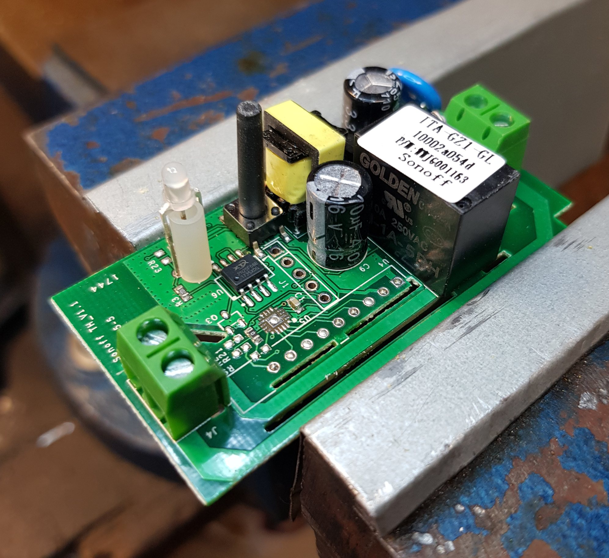
After stripping the PCB out of the case if you have a good look at it you will notice a row of 9 vacant spots for 1.4mm header pins to be soldered which are there for the RF model. You will also see the 5 vacant spots for flashing Tasmota (or whatever you may prefer) plus GPIO14.
Now I always use the flashing pins so I always need those fixed up and I often need access to 5V supply and occasionally extra 3.3V as well…and sometimes a little more? (COMING SOON)
So I have made it my normal practice to solder in two lengths of 1.4mm female headers into these two vacant spots. I prepare them like so. Including filing the ends to square them up again.


But sometimes there are problems with excess solder blocking the holes.

So I first fix that by using a solder sucker like this.

The pads are given a liberal amount of flux paste. And then after a few goes of heating and sucking the solder will be cleared from the holes. Although sometimes you do need to work on both sides.

Anyway now I move on to soldering in the headers. I usually fit them both and use a small piece of electrical tape to hold them in position as I turn the PCB over to solder them.
Pins are all fully through the PCB
Apply a liberal amount of Flux Paste and solder them all in.

And after that a good scrub in some methylated spirits.

Both headers are given a good inspection and this one is not one my prettier jobs.

For some reason the solder wouldn’t run down into the holes it just kept sucking up the pin…never mind they passed my standards testing and on with the next step. Which is…adding a 5V supply IN or if you need it a 5V supply OUT (when the sonoff is powered by 240V)…works both ways which is neat.
First I prepare some red and black wire as shown.

And then apply some flux to the diode marked as D5 and the pins I am going to use for my 5V power supply.

Then solder on to the D5 diode (taking careful note of polarity please). This diode takes quite a bit of heat to solder so if need be bump up the heat a bit for this job.

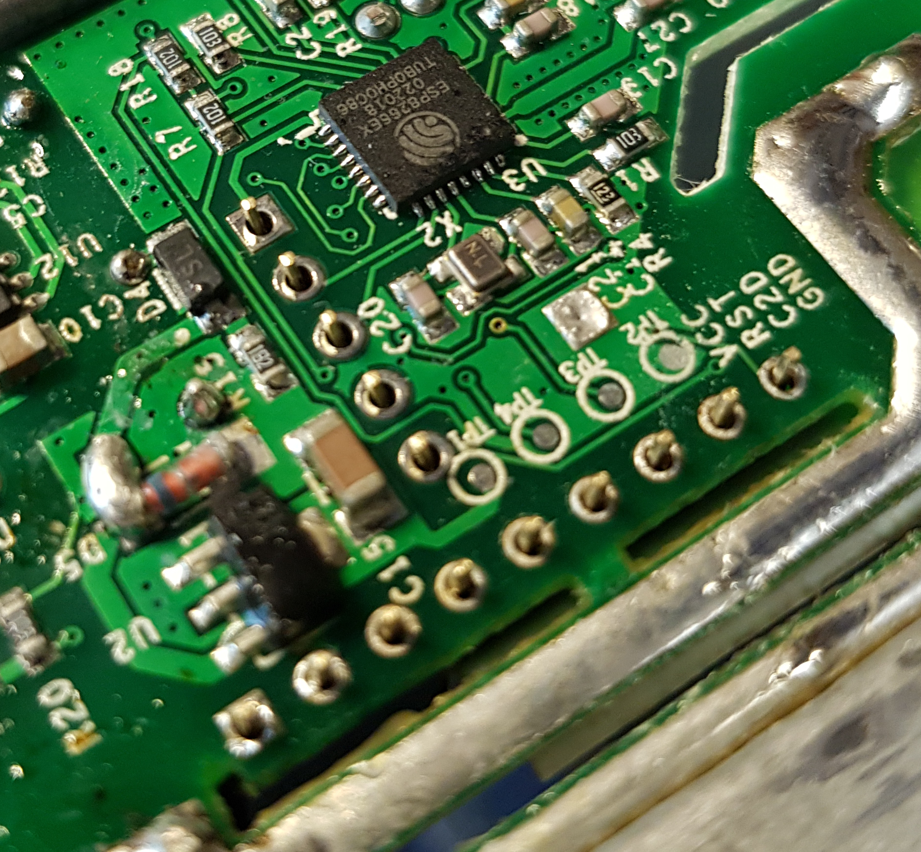
The photo is not so good but if you look at the black lead you may see I put a little 90° hook to give a bit better purchase around the header pin. Then they are both soldered on as shown to the 4th and 5th pins (counting from the GND and 3.3V end to the left). That should put the black wire opposite the end of the flashing header.

NOTE: This modification makes this device unsuitable to be powered by 240V
Another quite useful modification is to bring out the Button 1 (OR GPIO0) to the new header.
I start by soldering on a suitable wire to the surface mounted pushbutton. Flux paste is again required and this also requires a good bit of heat so again bump up your heat setting if need be.

After the wire is brought through to the other side of the PCB through the slot meant for 240V separation (thats why this makes this board unsuitable for 240V use now) turn the board over and continue.

Arrange the wire carefully to avoid any high components apply a good blob of flux paste and solder it on to the vacant new header pin between the Red wire on the 5V pin and the 3.3V pin.

Give the whole board another inspection at this point and dont forget to give it a good scrub in methylated spirits to clean up all the flux over the whole PCB. The main thing is to arrange the wires so they fit in between the components on the board wherever you can.
That completes this topic BUT…More posts are coming soon with details of how to use these modifications in example projects.
Below are a few photos of some of the equipment I use to do this sort of work.


Hope that is of help to some in the community here!
