So this is to run through my installation of Home Assistant OS on a Raspberry Pi 4, 4GB.
The Pi is in Argon40’s “Argon One cooling case with M.2”.
The guide overall will be my impressions of the case and M.2 attachment, sort of like a “use-case review” I guess. It will go through getting Home Assistant up and running, booted from the SSD in the case, and then go on to configuring Home Assistant to provide a wifi network for IoT devices to connect to that doesn’t pass them through to the internet, and hopefully to get fan control and power button configuration for the case working as well.
This is all being written up as I complete each piece of configuration and have stomped out the quirks, so check back often! I’ll change this line to reflect when it’s complete, and at that point make a more condensed version.
I don’t tend to post big things like this, so feedback on this spiel is most welcome as I’m sure I have lots to learn about publishing like this. Just be polite and not just trying to make me feel bad please ![]()
Current completed sections:
Background
Case overview and assembly
Imaging the SSD
Enabling the fan control
Automating the fan control
Pending Sections:
IoT wifi network
Backups
Updates
Background
Feel free to skip this blurb, just setting where we’re coming from here.
I’ve been running the Pi 4 in a original Argon One case since last year for Home Assistant. It’s been using a NVMe SSD I has spare (cause, y’know, THAT’s a thing), installed in a USB 3 to M.2 Orico case.
It was running Raspberry Pi OS, with Home Assistant installed in what I now know as the “Supervised” installation method.
How’d I get the Pi 4 USB booting so long ago? In a word, cheating:
- Set it all up in a multi-partition setup on a SD Card, then plugged it in to a computer with the SSD, cloned the main partitions to the SSD and deleted them from the SD card, leaving just /boot on there.
- Set up fstab on the SD card with the UUIDs of the SSD partitions so when it boots, 99.999% of the system runs from the SSD. Most importantly, all of Home Assistant runs of the SSD, so it’s really fast and responsive, and the database doesn’t wear out the SD card.
It’s a good SD card so it probably was never in any danger, but Once you go Flash, you never go back™, and BOY HAVE I GONE FLASH over the last decade. Only hard disks I have are in a DAS, and they’re slowly being replaced with SSDs too ![]()
I also have hostapd running a little Wifi network (figuring out that networkmanager, a part of Home Assistant, changes the MAC address all the time took me an awkward long amount of time) for IoT devices i expect to never get security updates and probably get hacked (like the Daikin, which sends and receives passwords and commands in complete plaintext, and the TV I can make display gifs on top of live TV from my phone).
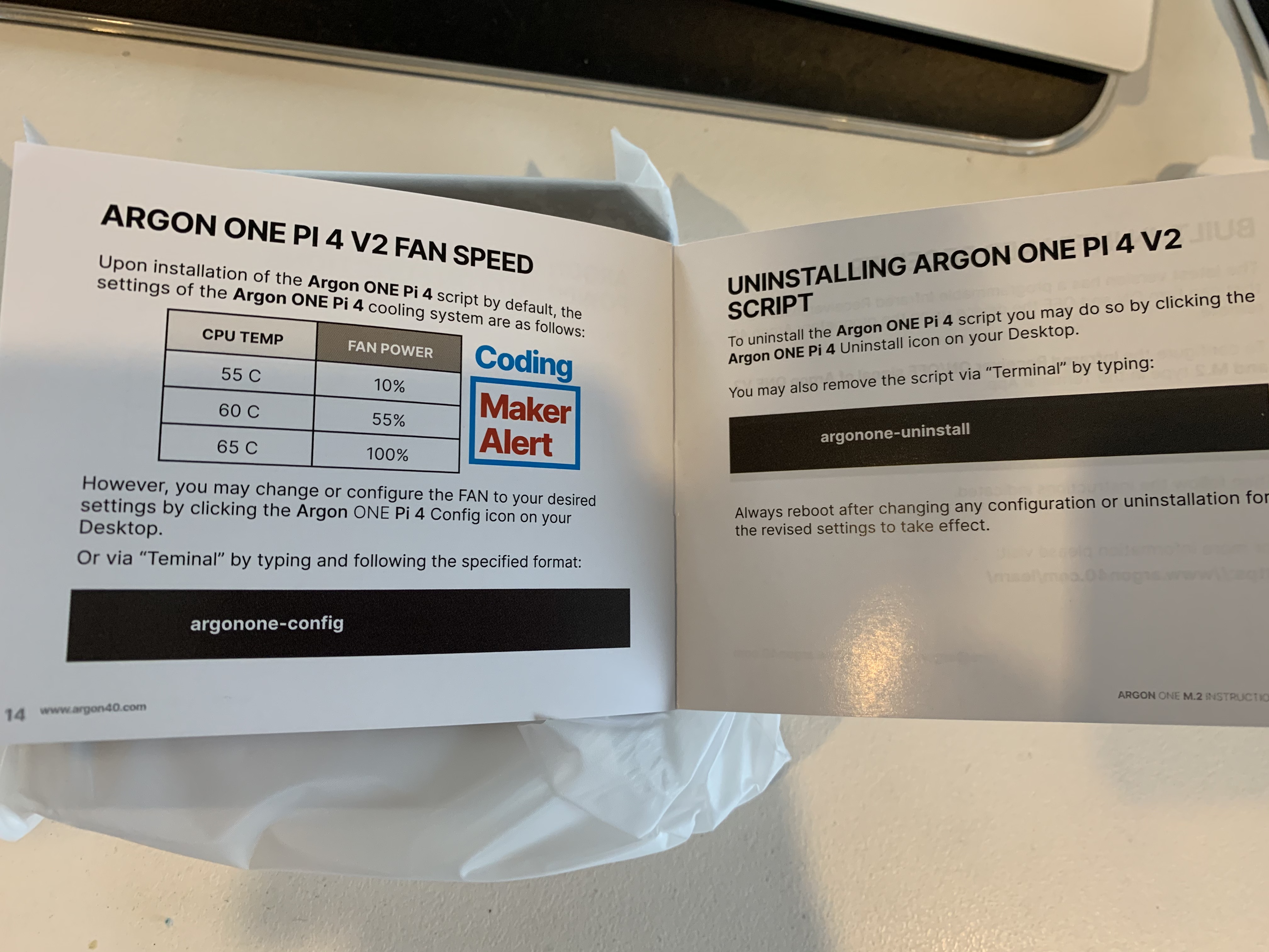
Finally, the fan control and power button config are run by a python script hooked into systemd. Thats all set up automatically by a bash script Argon40 hosts on their website. You can set what CPU temps trigger 10%, 55% and 100% fan operation (the defaults being a pretty sane 55, 60 and 65 degrees C), as well as the behaviour of pressing the case’s power button.
As you can see, a bit hacked together. It works well, except when it doesn’t. I always learn something new when something breaks, but I decided now that Home Assistant is definitely the core platform for my tech, and have been really impressed with it’s evolution over the last year, as well as the fantastic community that is growing around it.
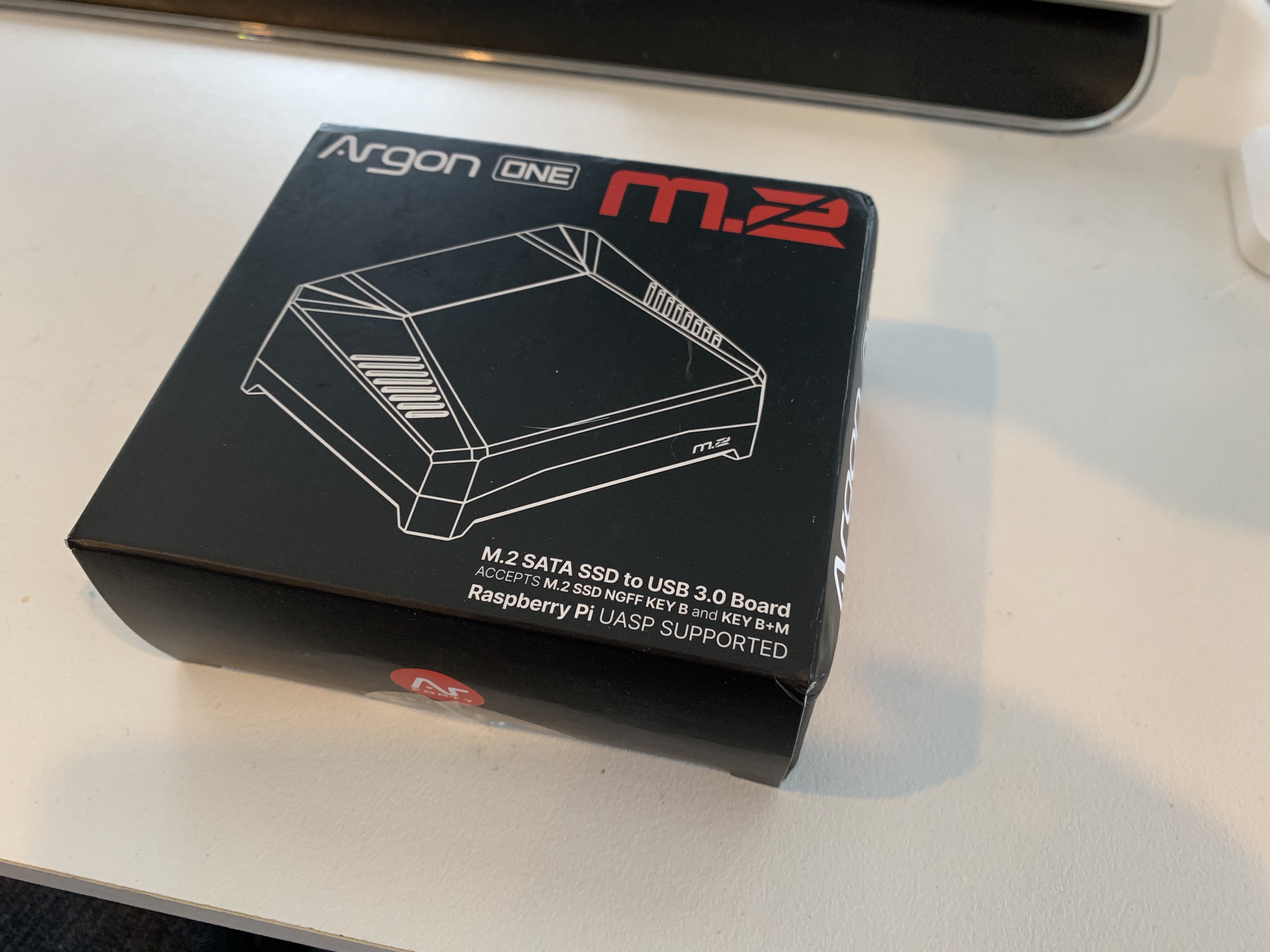
The new, shineh case!
So, meet the Argon One M.2 case:

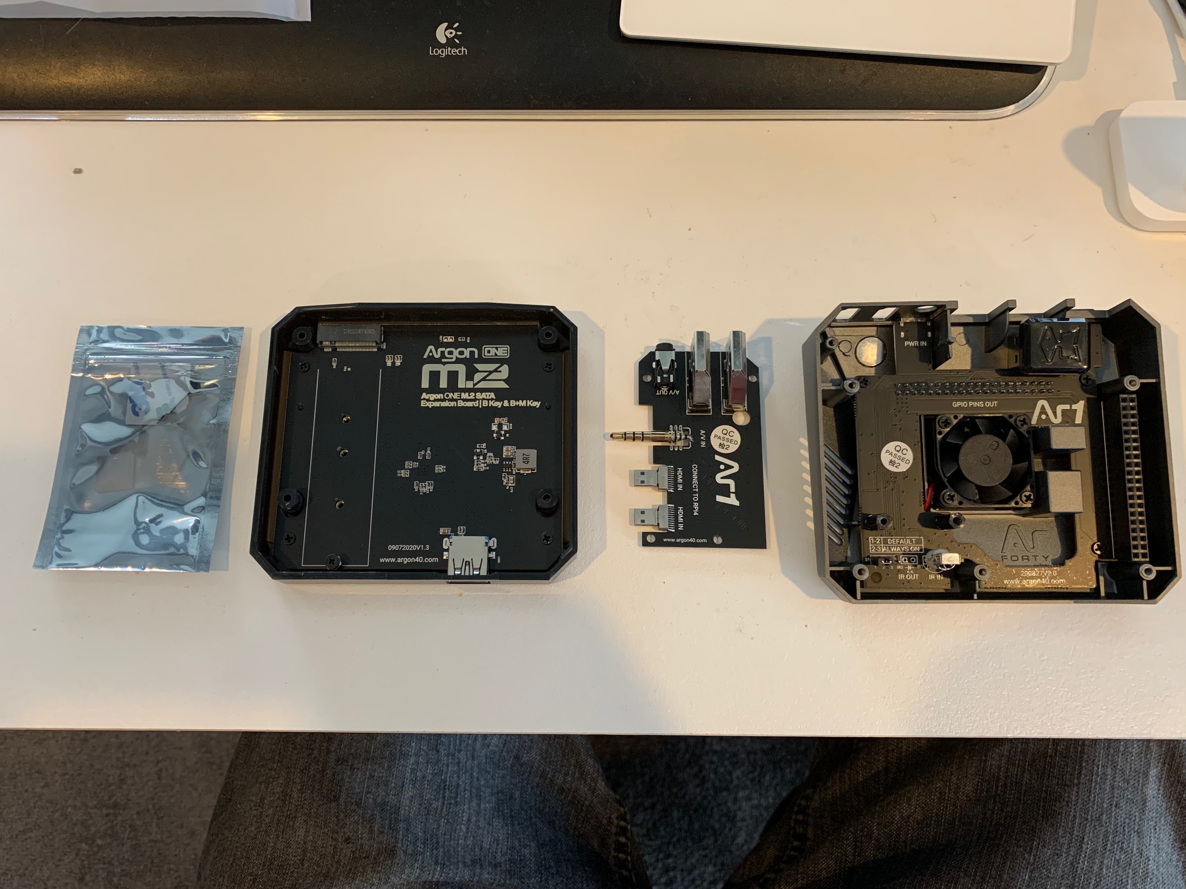
So here we have (left to right) the bagged screws, rubber feet and thermal pads for the heatsink (I know, THOSE are what get the ESD Bag???), the bottom section of the case, which houses the USB 3 to M.2 board, the A/V board, and finally, the Argon One case itself, with a second version cooling board, GPIO riser and power button controller.
The M.2 board takes up to a 2280 length M.2 SSD. It support SATA 3 SSDs, with a Key B or Key B+M pinout (the slots cut out of the SSD’s connector).
The A/V board takes the Headphone Jack and Micro HDMI ports, turns them on a right angle to point the same direction as the USB and Ethernet ports and, on this new version, makes the HDMI into full size ports, unlike the original Argon One, which kept the Micro HDMI form.
(Because of this, the Power button moves from above the HDMI on the original case, to above the ethernet port on the new case, for those keeping score)
A whole new case?
Here I should stress, you don’t NEED to replace the top half of the Argon One, nor it’s A/V board, if you have an original. You can buy the M.2 portion on it’s own and fit it to the original case. I got the whole new set for 2 reasons:
- Argon40 wouldn’t ship just the bottom piece to Australia. Not cost efficient in this crazy COVID world I guess. I needed to break 40 bucks before Australia was an option (and the shipping was then 8 bucks), and the full new case was actually the cheapest way to do that.
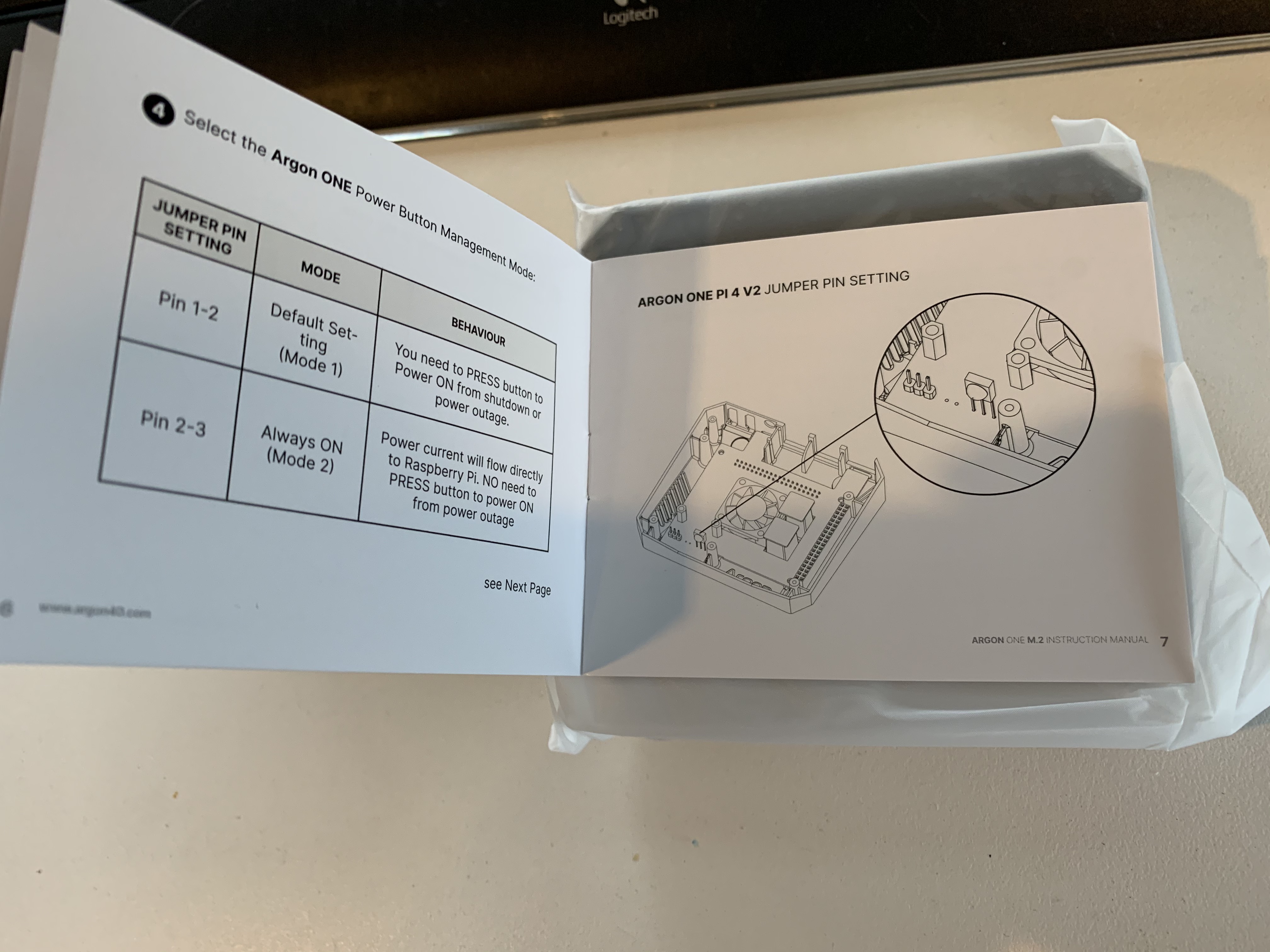
- As I had an original (like, ordered within weeks of their launch) case, and the case doesn’t cause the Pi to power on as soon as connected to power, you have to press the power button to turn it on after a power outage (cause power outages are often followed by power coming on for a few seconds, and then dropping again. Auto power on makes that 2 unclean shutdowns for the price of 1!).
I plan for this to move off my desk and into a cabinet with my router, and it won’t be easy to get to to turn on after a power outage.The new cooling/power board in this new case gives us a jumper to opt in to automatically powering up when power connects.

Bonus, the new board has an IR receiver. Don’t think I’ll need it, but you may find this useful!
(the old board has sockets you can add an IR receiver and transmitter, but nothing pre-installed)
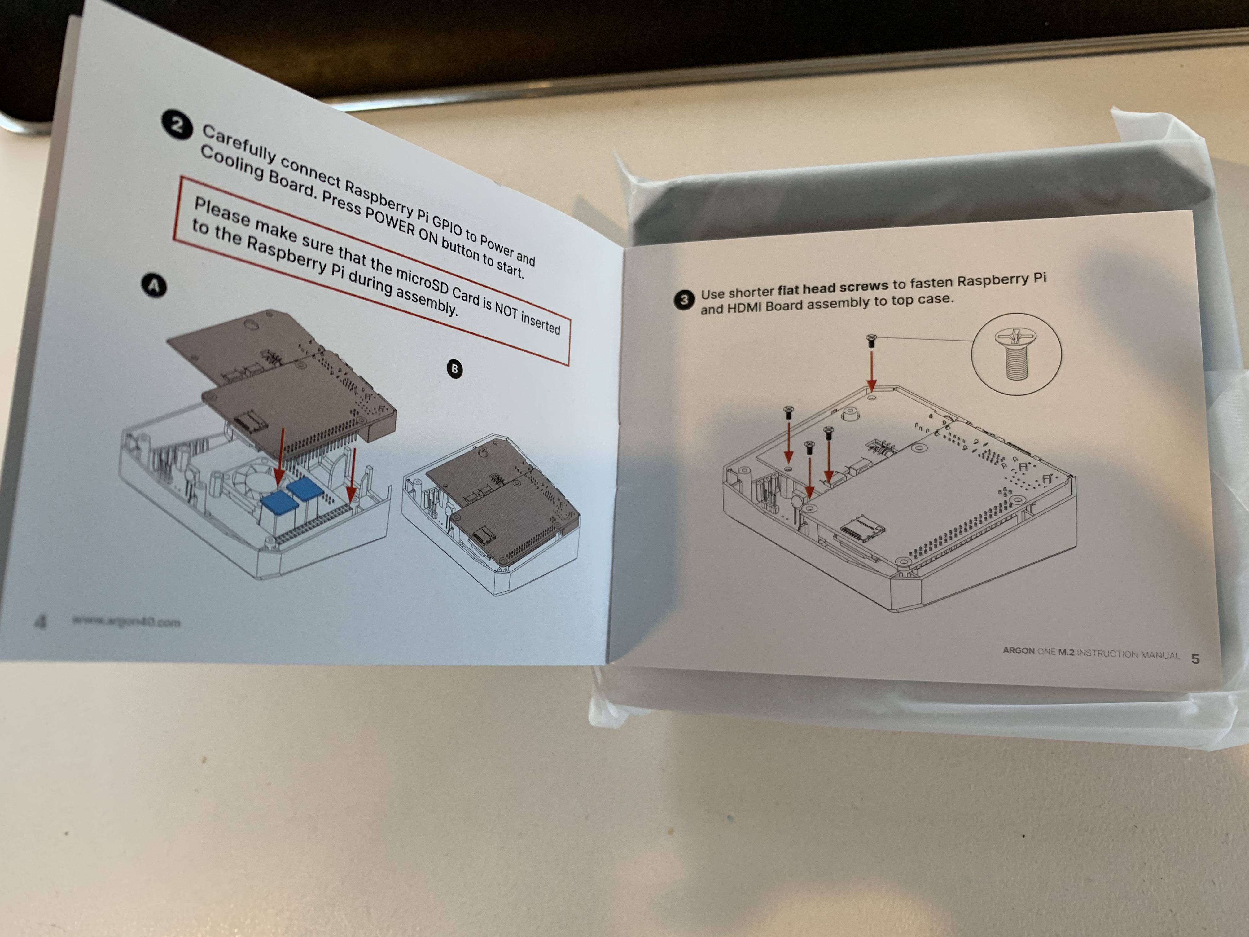
The Manual
I haven’t seen this online yet, even on Argon40’s website, so here is the manual, page by page


Ok, on with it then
The SSD I’ll be using is a Crucial MX500.
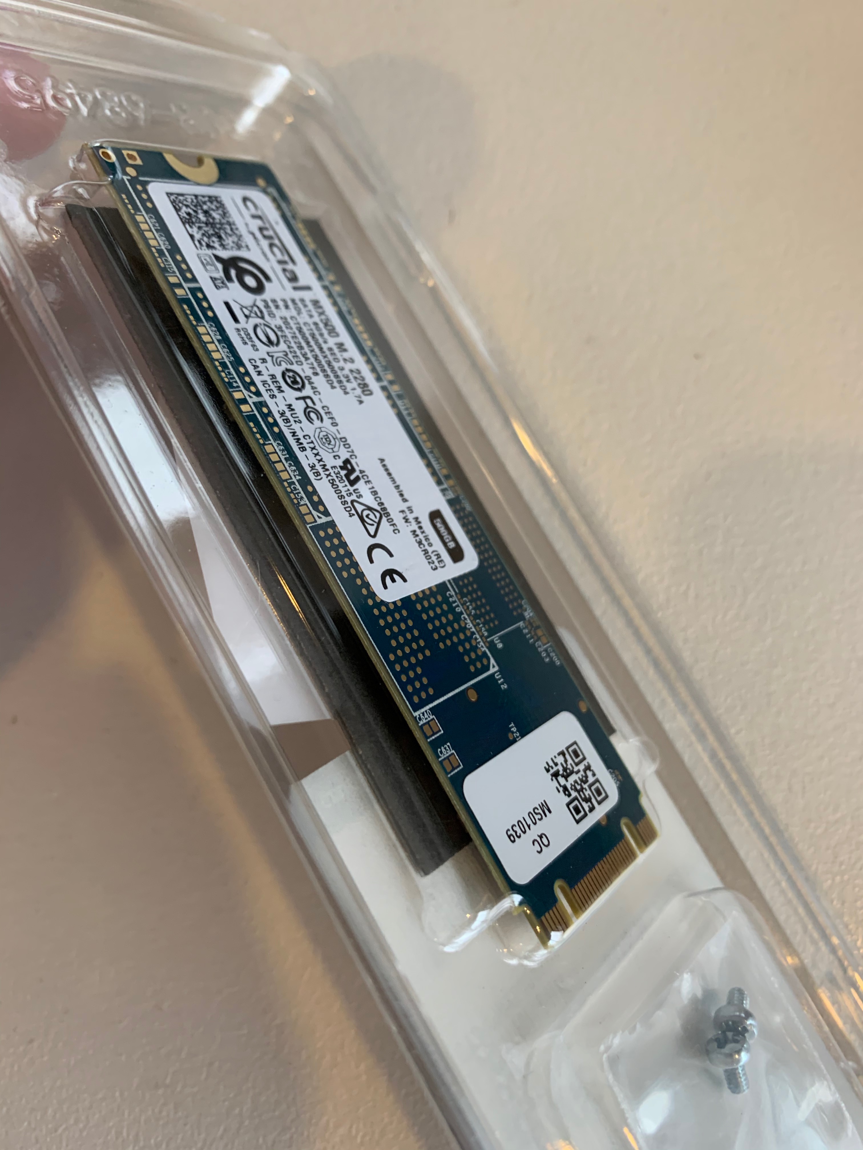
It always amazes me how thin the boards on M.2 SSDs are, I feel like I’ll snap it with the slightest touch.
The SSD comes with 2 screws (in case you lose one I guess) and a copy of Acrontis True Image. Thanks guys, but we won’t need it in this case.

… and I guess we won’t need the screw. The Argon M.2 Board comes with a screw pre-installed. It also has a removable Hex bit that can be undone with a hex driver or some careful pliers. I didn’t need to here, but by taking it out, you can reinstall it in other mount points for shorter M.2 SSDs if you need to (2260, 2242 and 2230 length cards to be exact).
Unlike a lot of other SSD enclosures I’ve used, the hex bit didn’t hang onto the screw unnecessarily when the screw was undone, which I consider good attention to detail on their part.
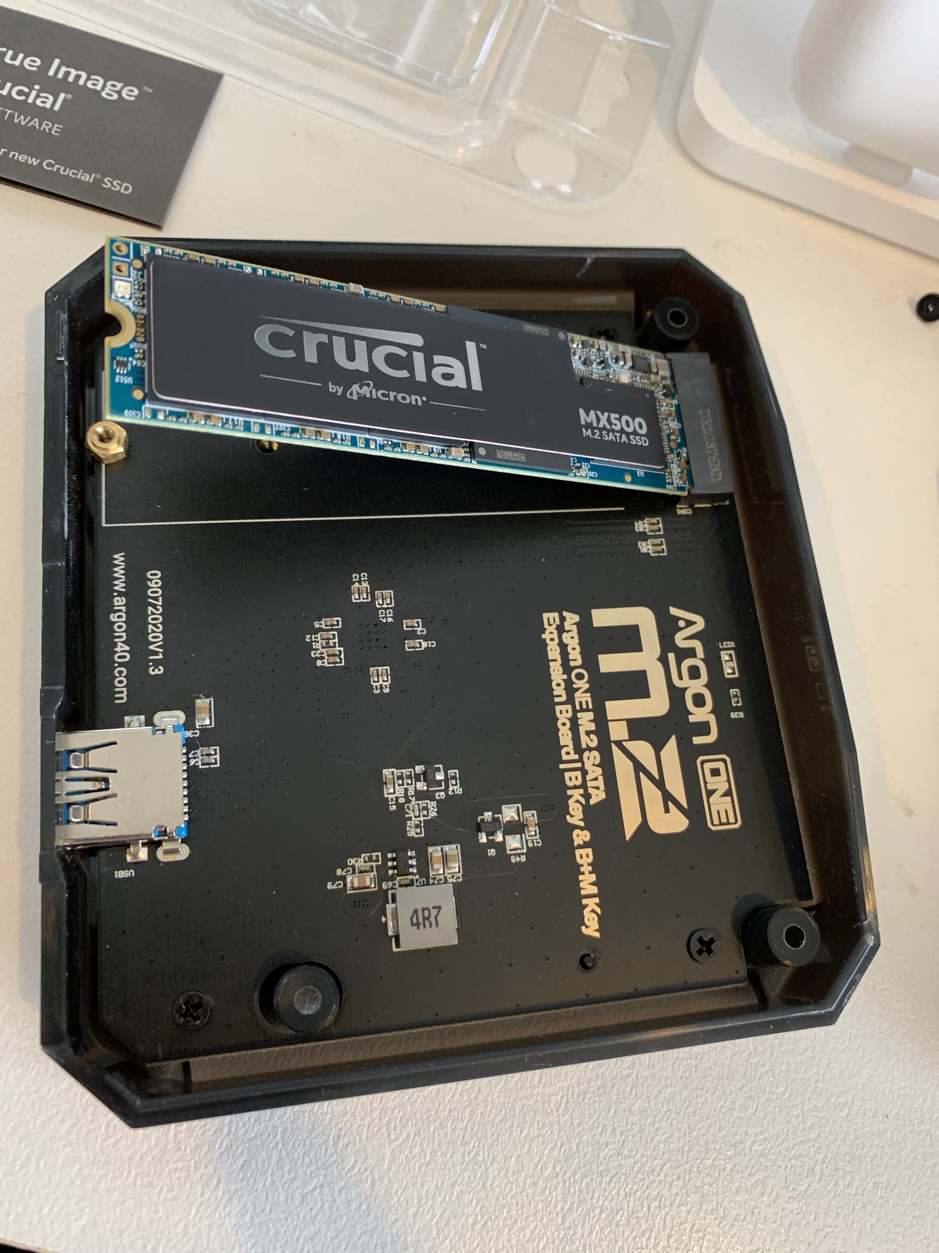
Doesn’t it freak you out when they sit up like that? On the other hand, this will make removing the SSD much easier if that’s ever needed.
Now for the weird part.
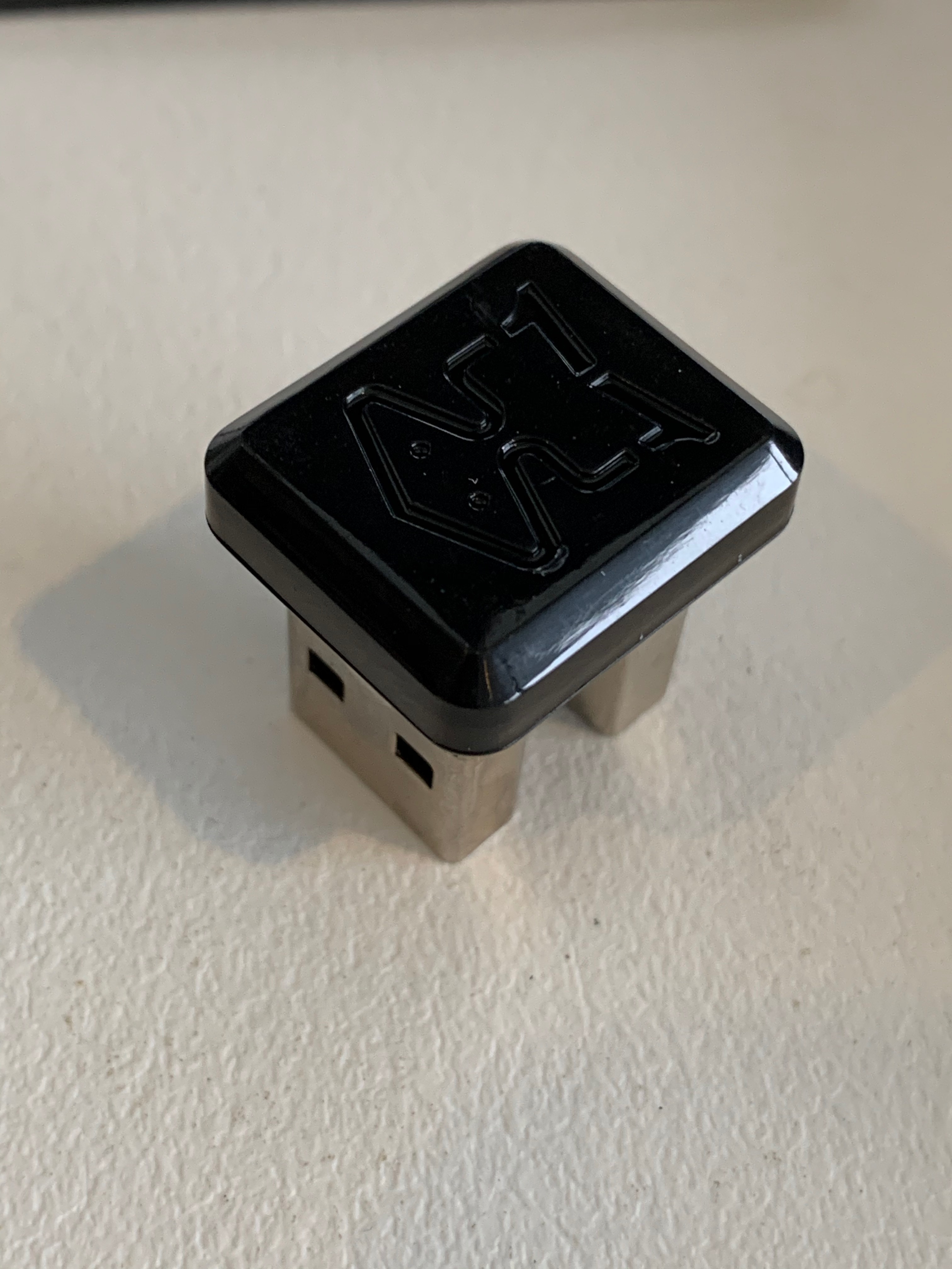
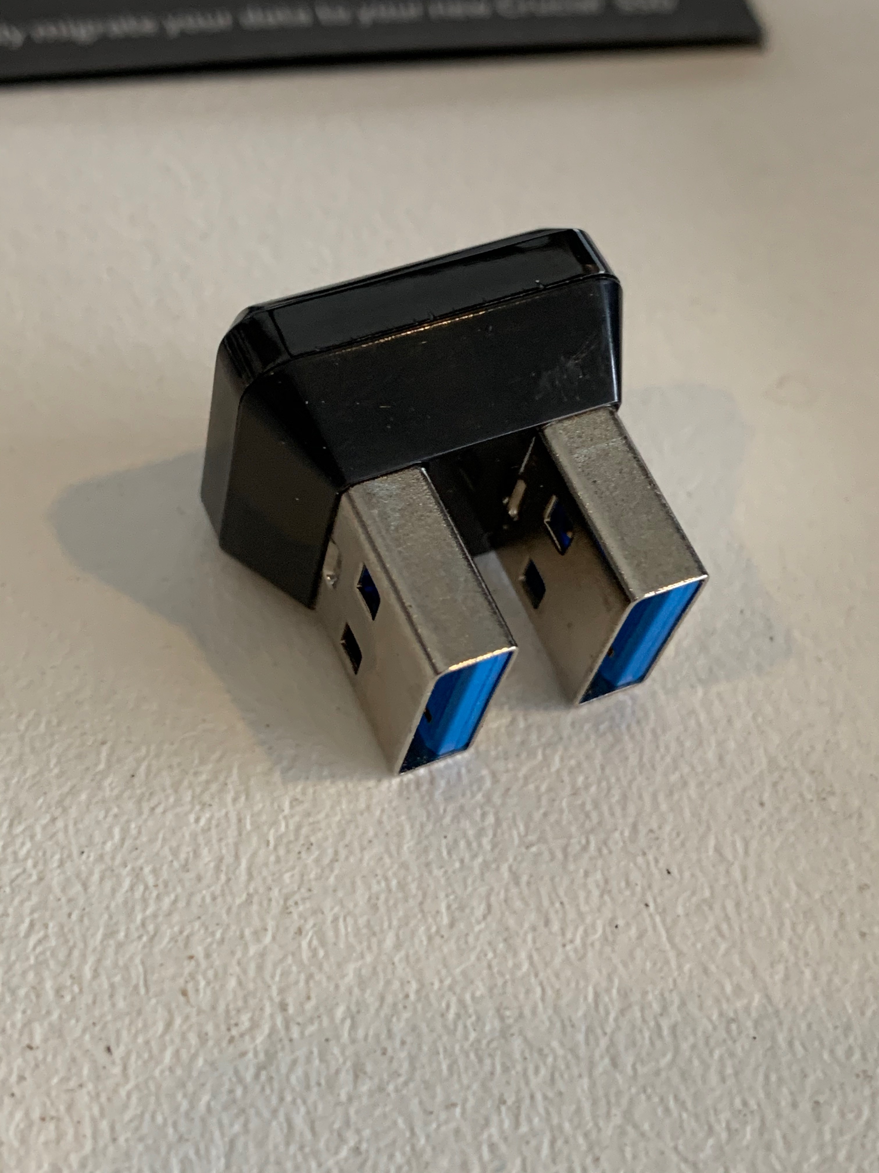
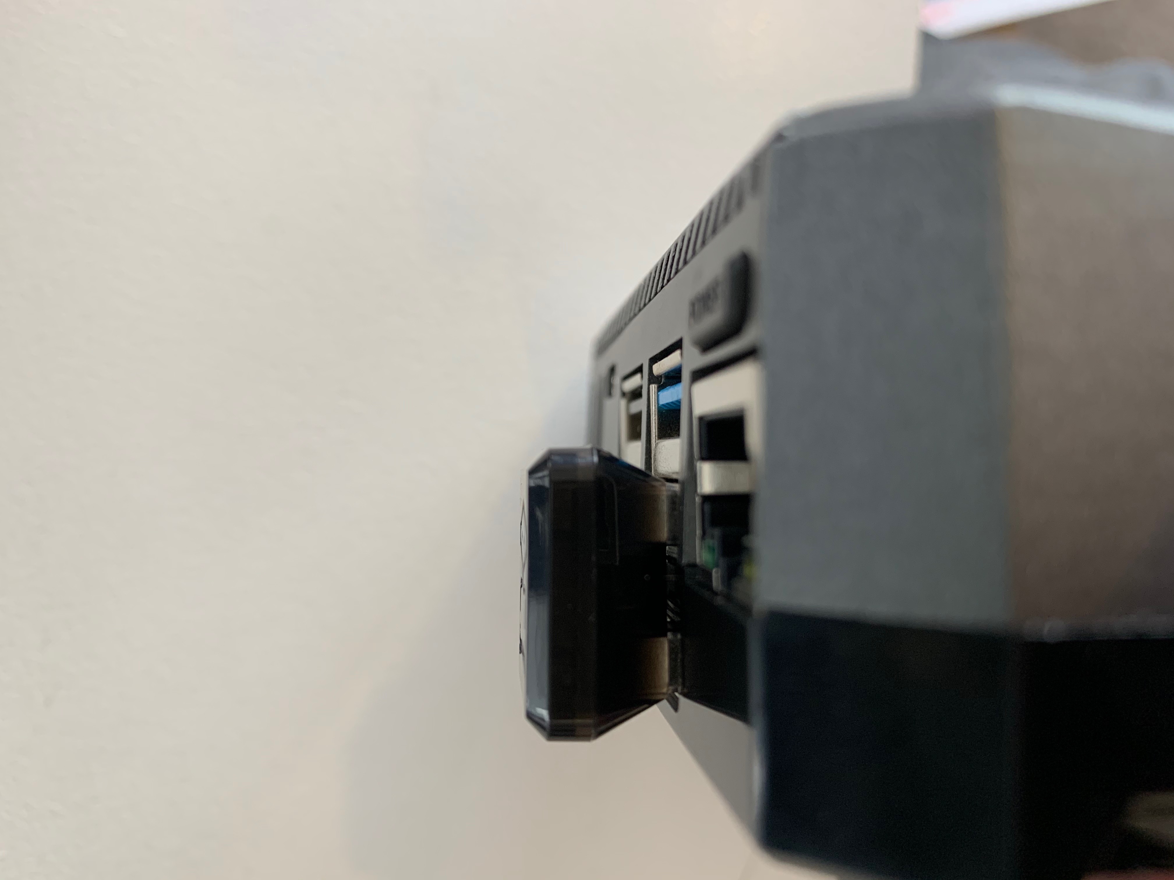
Since we got the SSD for speed, having it connect via GPIO would be silly. This is the USB A male to male connector that links the M.2 board to the bottom USB 3 port on the Raspberry Pi. Unorthodox, but clever! Certainly compact, so you won’t have a cable looping out and back that could accidentally get pulled out.
Update 26th Nov: As i’ve used it more and more, the USB connector has proven really solid, and it’s odd shape actually has turned out to be great for grip and getting it in and out straight and easy. I was a little skeptical about it at first, thinking it was a bit overdone but now I totally get it. Good fob folks!
Here are the two cases side by side for comparison:

Sorry bout the thermal pads, I swear I’m usually cleaner than this.
So, differences:
- The power botton moved from the top left corner to the top right.
- The fan connector is now on the in-accesible side of the board, so it’s harder to replace if needed. That said, I’ve been running this for a year straight and not needed to, soooo…
- The power mode jumper.
- The IR receiver is now pre-installed. (you can still add a transmitter, if you want to control anything this way)
As far as I’ve been able to tell over the time I’ve been using it, the slots on the left and right are air intake. The fan doesn’t actually run that much, even through it’s above a perpetually running hot Mac Mini. ![]()
Even through I live with 2 cats, who no matter what I do like to walk around on my desk, which includes very close to this Pi, the case isn’t caked with fur, a big relief!
The A/V Board
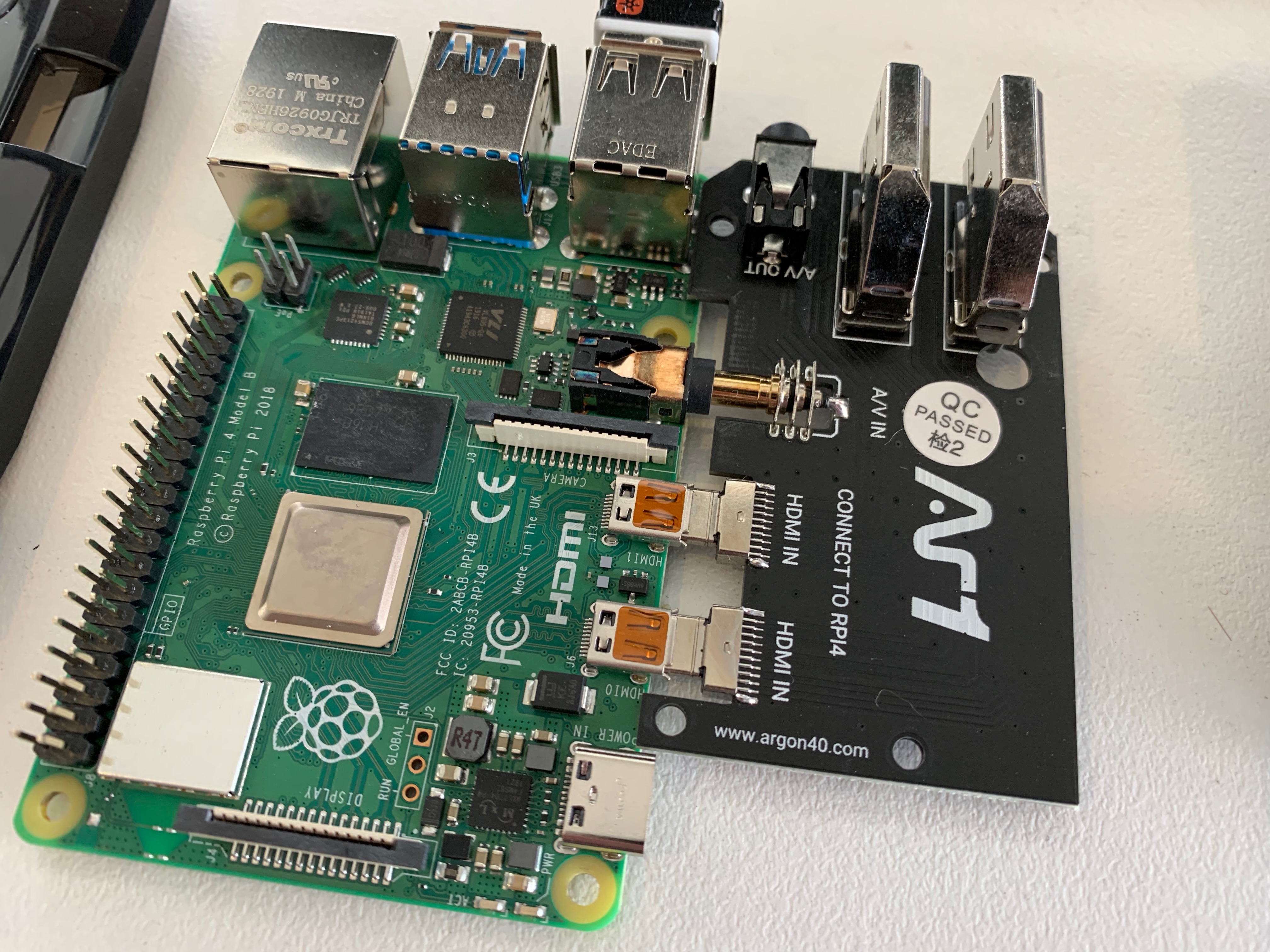
So the A/V board just plugs in to the side of the Pi, pretty easy.
It is a little off-putting through, as the plugs are all much longer than normal, since there is no cable necks on them. I promise, this IS fully inserted.
Bits and Bobs
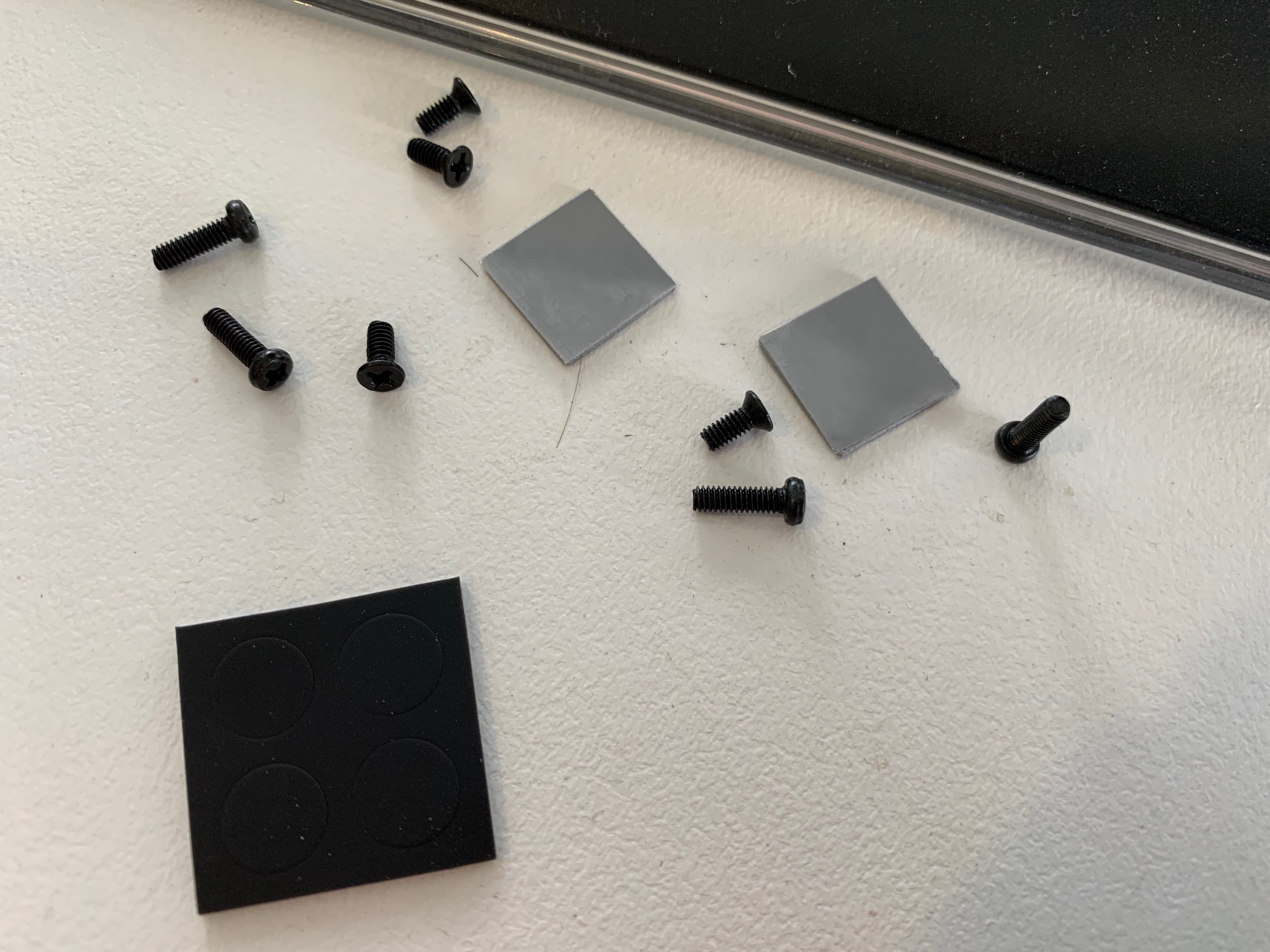
So there are 4 short screws that are installed into the case, 3 for the A/V Board and 1 for the Pi.
There are also 4 long screws, for installing the bottom case and M.2 card to the top of the case.
There are 2 thermal pads, one for the Processor, and one for the RAM. Finally, there is a set of 4 feet, to pop out of that black sheet at the bottom.

The pads are both just squares, even through the RAM is a rectangle. The heatsink acknowledges this. I left the extra material as it was anyway. On the original case, it didn’t cause a problem, and I am lazy ![]()
Assembly
This is somewhat brief. Basically you just gently rest the Pi and A/V Board upside down in the case, carefully lining up the GPIO pins.
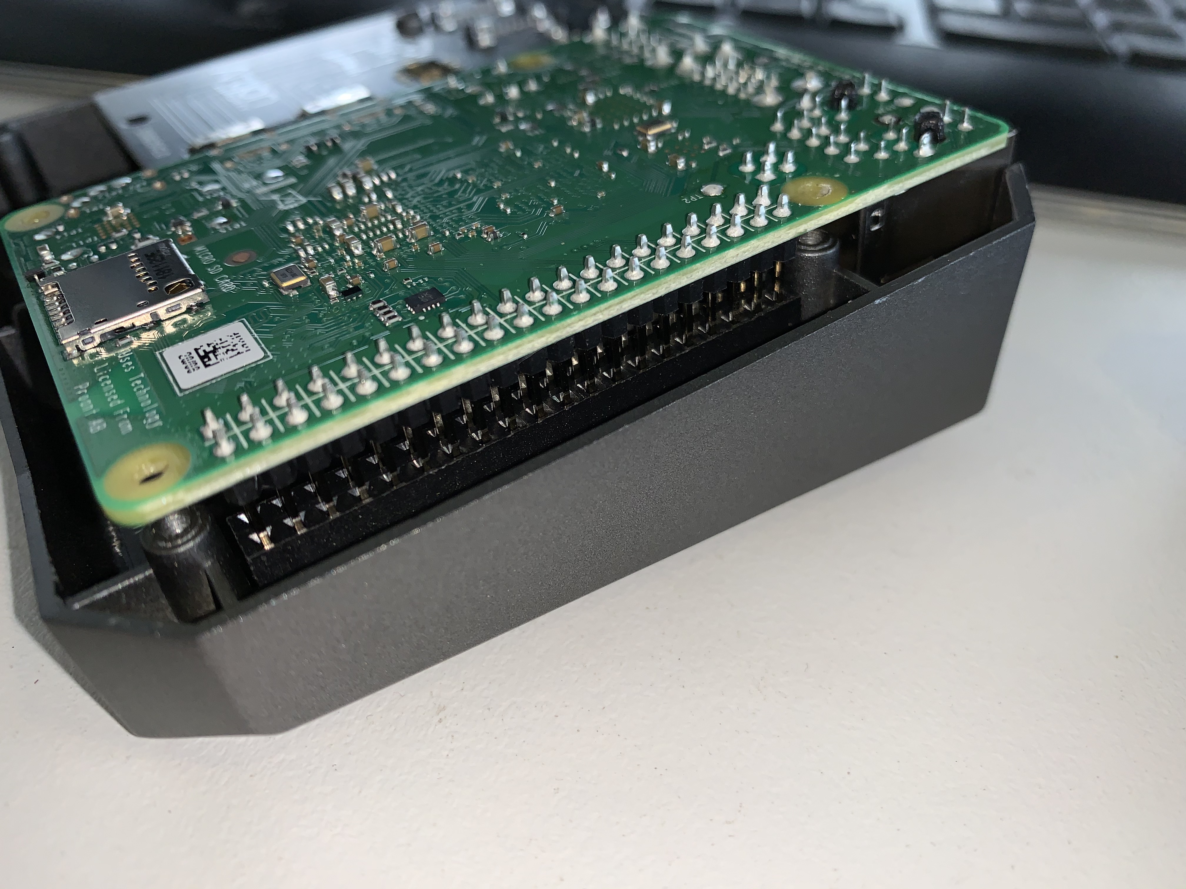
Once you are sure they are lined up right, loosely install the screws in the correct holes for the Pi and A/V Board, then then press down the Pi onto the GPIO. This provides most of the grip for the Pi to the case until we get the bottom on, and definitely holds the board to the heatsink posts.
Unlike the first case, you install the SD card before attaching the bottom case on this one.
- I’m thinking they had complaints of people forgetting to remove the SD card before removing the case and breaker this card, or worse, their card reader on the Pi.
- A little annoying if you wanted to be popping the card in and out, but otherwise not a problem really.
Tighten up the screws and then just put the M.2 card and bottom case onto the bottom of the enclosure and install the 4 long screws. Make sure the USB port on the bottom case is aligned with the USB ports of your Pi.

So it seems big and unwieldy, but the adapter does actually leave enough room for things to plug in around it (generally). It’s also very secure.
If you’re worried about something being in the USB 3 port above it, I’d suggest an extension cable, or cable to a USB hub, as that will fit fine, but some adapters (think wifi, zwave, card reader etc) might be too bulked to directly attach.
Honorable Mention
As you might had noticed in the photos, the Cooling board also passes through the GPIO pins to the top, which are tucked away under a magnetic cover.
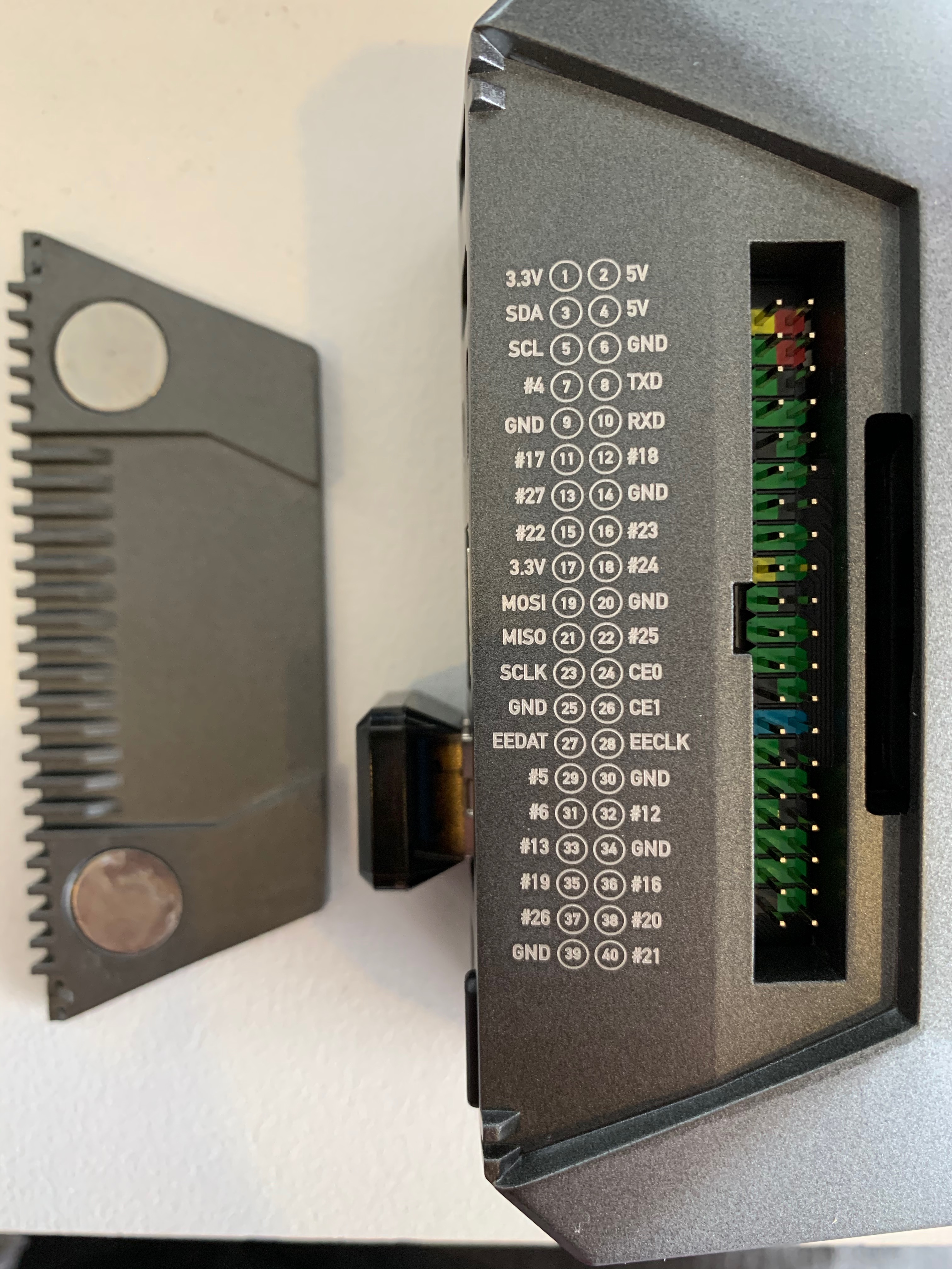
I really like the reference diagram along with it. You can either run jumper cables out, or install (most) GPIO hats here.
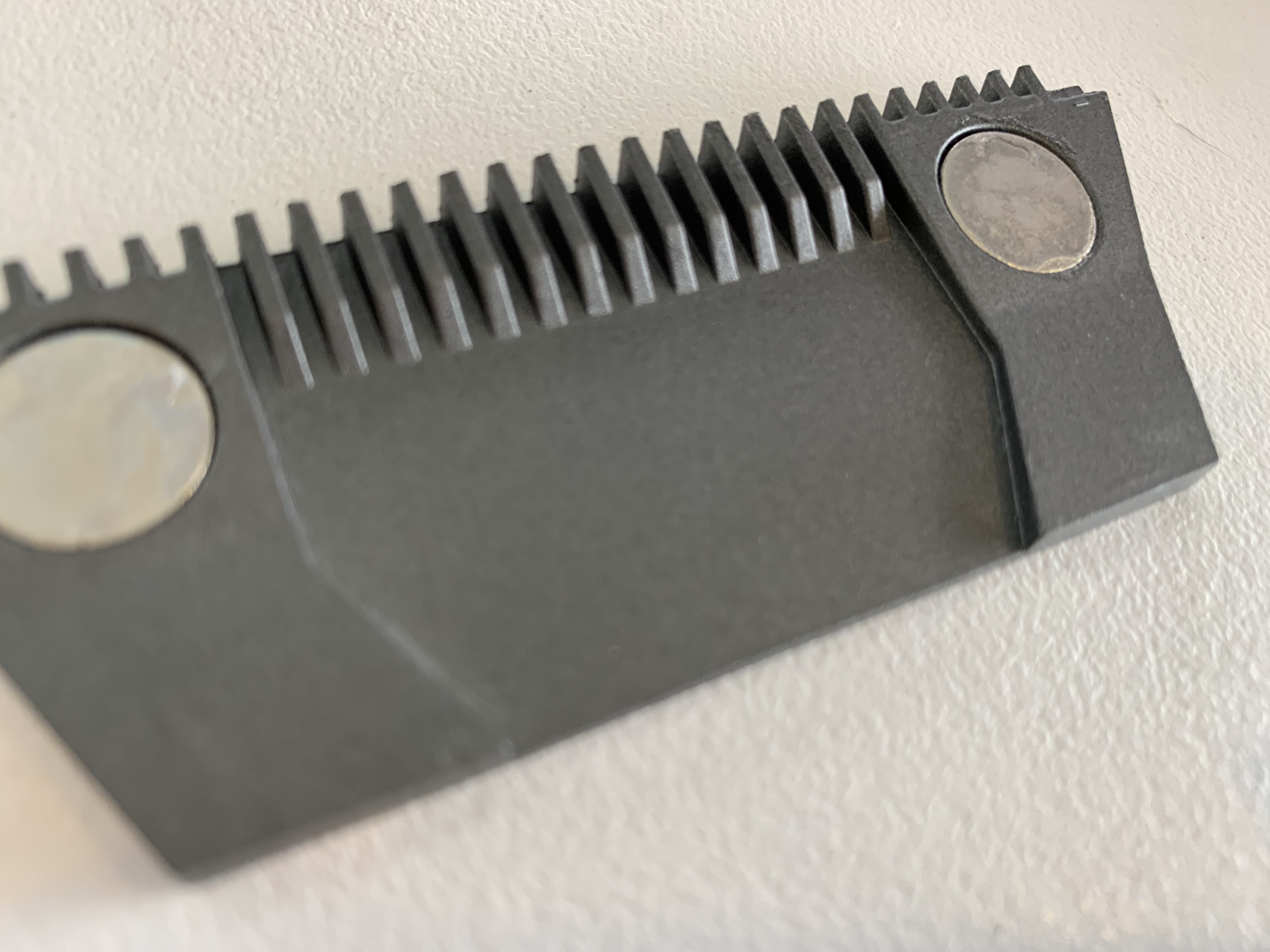
I have seen photos of people using the grill in the magnetic section to route jumper leads of the I/O, but don’t do this please. With that cover installed, those grooves are the fan’s exhaust…

Onwards, to Home Assistance!
I’m working on this bit now, should be a couple more hours ![]()
So I’m going to skip over updating the Raspberry Pi firmware, it’s basically just install Raspberry Pi OS on a SD card, and then run your software updates as normal, as the USB-Boot firmware is now in their Stable branch and should be pushed to everyone.
Jörg Wagner’s excellent guide covers it in great detail pretty early on if you want to have a look! That guy really knows how to write a great guide!
I will steal one little bit from him, for how to check what version of the firmware you’ve got, and how to set the boot order to USB first:
So, we now need to image Home Assistant OS onto the SSD. We’ll be using the development version of the OS, since that is where USB boot support is.
As of this writing, version 5.5 is out, which I haven’t seen complaints about from Pi 4 users with SSD boot drives, so hey, let’s dive in:
 Releases · home-assistant/operating-system
If you have another enclosure to put your SSD in and image the drive from your PC or Mac, or if you have a USB 3 male A to male A cable, feel free to use Balena Etcher, or your similar tool of choice.
If you’re like me and don’t have such a cable, or spare enclosure, come on a ride with me as we do this via the Linux terminal on your Pi. (I’m assuming you have a running copy of Raspberry Pi OS or Debian on a SD card or other USB, so you can do this on the Pi)
Downloading the image from Github using wget
As you scroll through that page, you want the latest development build, currently “Development 5 Build 5”. Click the “Assets” section, and look for the “hassos_rpi4” image that ends with “.img.gz”. I downloaded the 64-bit version, through apparently if has issues with GPIO. I hope to work through these myself, and will include anything I do to get it working here.
The 32-bit version doesn’t like SSD booting. Thanks to Anwenderfehler for letting us know!
Right click, and copy the link. In the terminal on your Raspberry Pi, type wget and then paste the link. for example:
wget https://github.com/home-assistant/operating-system/releases/download/5.5/hassos_rpi4-64-5.5.img.gz
Next, we need to extract the gz archive:
gzip -d hassos_rpi4-64-5.5.img.gz
Impressive, 300mb from 2gb. Dat compression tho!
Now, we need to work out what device our new SSD is. lsblk is a good command for this. It will display our connected devices, as well as any partitions and mount points of them in a nice tree:
pi@hassio:~ $ lsblk
NAME        MAJ:MIN RM   SIZE RO TYPE MOUNTPOINT
sda           8:0    0 465.8G  0 disk
└─sda1        8:1    0 465.8G  0 part /
sdb           8:16   0 465.8G  0 disk
mmcblk0     179:0    0  59.5G  0 disk
├─mmcblk0p1 179:1    0   256M  0 part /boot
└─mmcblk0p2 179:2    0   1.9G  0 part
So for me, my new SSD is sdb. Pay close attention here for your results, as if we get things wrong with this and you could wipe a drive. Keep backups, and have any drives that don’t need to be connected detached, so they are safe. Here the mmcblk0 device is my SD card, and sda is the SSD I’ve been running up till now.
Now I know what device I’m imaging, lets get into Disk Destroyer! ![]()
dd (which doesn’t actually stand for that but could certainly live up to the name if needed) can image the .img file onto the drive to get us going.
Please make sure to change the “/dev/sdb” to be correct for your system, you’ll have a lot of trouble if that is wrong!
dd bs=4M if=hassos_rpi4-64-5.5.img of=/dev/sdb status=progress conv=fsync
You might need to run this with “sudo” at the start, depending on what user account you are in and how your existing OS is set up.
To break this down a little:
bs=4mis the block size. if 4M doesn’t work for any reason, try 1M, but it will be slower.if=means “input file equals”, and we follow that with the name of the .img fileof=means “output file equals”, and we give it the device path of the SSD. In the *nix world, everything is a “file”, even a SSD.status=progressgives us semi-regular progress updates. The priority is for writing the disk so it might seem to freeze and unfreeze, but overall you can know it’s not TOTALLY locked upconv=fsyncmakes sure that any caches are pushed to disk before the command completes, so no data is missed.
You should see something like this:

The big moment, rebooting
So now we get into what we’ve been waiting for. Booting Home Assistant OS.
You’ll need to remove the MicroSD card if it is still installed, so shut down the Pi and remove the bottom case. Remember to unplug the USB header between the Pi and the bottom case, or it’ll fight ya! Pop out the SD card and reinstall the case and USB header, and then start-errup!
Yup, we’ve got a bootable Home Assistant. Not so hard, right? Head to homeassistant.local:8123 in your web browser on another computer and (so long as you connected via ethernet, or set the wifi settings as per the Getting Started Guide, we’re rolling!
“But wait”, I hear you say. “What is that faint whirring noise?”
That, my friends, is the Argon One’s fan.
We now are not running any software to feed the CPU temperature through to the Fan/Power board, but because it is supplying the power to the Pi, it knows the Pi is on. Like any reasonable cooling system, it assumes it should run at least a bit until someone tells it what the temperature actually is. At least that way, no one can blame it if the Pi melts.
So let’s get to installing some controller support for the Argon One’s fan and power button (as a bonus).
Hackin’ together fan support
Fortunately, a wonderful person has already made a custom component for the Argon One case, as well as the Fan HAT. Round of applause for Misiu, if you please!
Github: Misiu - Argon One Pi 3 & 4 cases and Fan HAT support for Home Assistant
It keeps it basic, allowing 3 fan speeds (just like Argon40’s software), and it also allows you to trigger an action in Home Assistant by double clicking the power button. Nifty!
You’ll need a file editor, and chances you’ve installed the Official Home Assistant File Editor. Start up the add-on and lets get this running.
Browse to the folder with your “configuration.yaml”. If this is the first time you are opening the file editor, you should already be there, but double check you’re there. Create a folder called custom_components, and then add another folder inside that called argon40.
In this folder you will want to create 4 files:
__init__.pyconst.pymanifest.jsonservices.yaml
Next, we will need to copy the contents of each file from GitHub into the corresponding file in Home Assistant. Open the init file on Home Assistant, and then copy and paste the contents from this GitHub Raw File Link.
We will need to do the same for const (Raw Link), manifest (Raw Link) and services (you guessed it, Raw Link)
Once those files are saved, go to Home Assistant’s “Configuration” page, then “Server Controls”. Hit "Check Configuration to confirm we haven’t done anything that would stop the Pi booting, and then if it checks out, tap “Restart”.
Once restarted, we need to jump back into the file editor, and select our “configuration.yaml” file, and add the line:
argon40:
Restart Home Assistant once more and…!
Nope, we’re not done yet. You’ll see a notification from Home Assistant telling you there was an error loading the component “argon40”.
So what’s going on.
Well, the argon40 component needs the i2c bus (part of the GPIO connector on your Pi), which is not enabled by default in Home Assistant OS.
Since Home Assistant OS is a tightly managed environment (which is a big part of the reason we would use it over the Supervised install), we can’t directly enable i2c from Home Assistant or even the SSH add-on.
The good folks at Home Assistant have a basic guide, but I found the ssd didn’t auto mount when I went ahead with it.
So we want to shut down the Pi, and pop the case open again to reinstall the SD Card with Raspberry Pi OS on it. Leave the SSD unplugged until the Pi finishes starting up.
I was going to find the mount point for Home Assistant OS’s boot portion using lsblk, but it turns out it hadn’t mounted on it’s own:
pi@hassio:~ $ lsblk
NAME        MAJ:MIN RM   SIZE RO TYPE MOUNTPOINT
sda           8:0    0 465.8G  0 disk
├─sda1        8:1    0    32M  0 part
├─sda2        8:2    0    24M  0 part
...
sdb           8:16   0 465.8G  0 disk
└─sdb1        8:17   0 465.8G  0 part /
mmcblk0     179:0    0  59.5G  0 disk
├─mmcblk0p1 179:1    0   256M  0 part /boot
└─mmcblk0p2 179:2    0   1.9G  0 part
Which left me wondering, which partition is which? Since sdb is the root partition (“/”), the Home Assistant SSD must be sda here, but still so many possible partitions to choose from.
The “parted” command helps here. We run “sudo parted /dev/sda” to open the SSD in parted, and then when we get to the “(parted)” prompt, type “print”:
pi@hassio:~ $ sudo parted /dev/sda
GNU Parted 3.2
Using /dev/sda
Welcome to GNU Parted! Type 'help' to view a list of commands.
(parted) print
Model: Argon Forty (scsi)
Disk /dev/sda: 500GB
Sector size (logical/physical): 512B/4096B
Partition Table: gpt
Disk Flags: pmbr_boot

Number  Start   End     Size    File system  Name              Flags
 1      1049kB  34.6MB  33.6MB  fat16        hassos-boot       msftres
 2      34.6MB  59.8MB  25.2MB  ext4         hassos-kernel0
...
 8      731MB   500GB   499GB   ext4         hassos-data
Ok, sda1 is what we are after. Type “quit” to exit parted. If it asks you to save or commit any changes, then only do so if you intended to change something.
Next, we need a mount point for the boot partition. Basically an empty folder that all the contents of the boot partition can appear in:
sudo mkdir /media/hassboot
And now we can mount the partition to that folder:
sudo mount -t vfat /dev/sda1 /media/hassboot
Tada!
pi@hassio:~ $ lsblk
NAME        MAJ:MIN RM   SIZE RO TYPE MOUNTPOINT
sda           8:0    0 465.8G  0 disk
├─sda1        8:1    0    32M  0 part /media/hassboot
Now hop into that folder (cd /media/hassboot) and we just follow the steps in the “Enable I2C” guide above:
pi@hassio:/media/hassboot $ sudo mkdir CONFIG
pi@hassio:/media/hassboot $ sudo mkdir CONFIG/modules
pi@hassio:/media/hassboot $ sudo nano CONFIG/modules/rpi-i2c.conf
In nano, we want to enter the three driver packages for the i2c to be enabled. In order, these are for the chip at the heart of the Pi, the implementation of the chip, and the generic /dev entries:
i2c-bcm2708
i2c-bcm2835
i2c-dev
One you’ve entered those in, press “control-o” on your keyboard to save and hit the return key (err, enter) to confirm, and then press “control-x” to exit nano.
Now we open the “config.txt” file
pi@hassio:/media/hassboot $ sudo nano config.txt
This should already be populated with settings, although many of them are commented out (the # at the start of those lines).
I added a section after the line starting with “kernel…”:
# Enabling i2c for Home Assistant OS & Argon Case
dtparam=i2c1=on
dtparam=i2c_vc=on
dtparam=i2c_arm=on

# Also reducing SD card polling, since we're on a SSD
dtparam=sd_poll_once=on
Why bother about the SD Card polling?
While I was doing research for this, and looking through threads for people getting Raspberry Pi OS running on the SSD, a lot of people were reporting that leaving the Pi checking the SD slot lead to moderate bumps in CPU usage, which is power wasted and heat generated, so may as well turn it off. This will only apply when booted from the SSD, it doesn’t stop you disconnecting the SSD and inserting an SD card.
Once again, “control-o” and return to save, “control-x” to quit. Shut down with “sudo shutdown now”.
Pop the bottom case off the Raspberry Pi again and remove the SD card, then re-assemble and boot up with Home Assistant OS from the SSD.
On the first startup, Home Assistant reads the contents of the “CONFIG/” folder we created, and then configures itself based on that.
Once it has fully started up, you will need to reboot the Pi so that it can use the modified configuration and get the i2c working. Head into the Supervisor, click the “System” tab and in the “Host System” box, click reboot.
Configuring the fan
Seems like a let-down, there’s nothing new in the UI!
The argon40 component we’ve just configured sets up a service, which doesn’t immediately appear in the UI. If you click “Developer Tools” in your sidebar, and then the “Services” tab, you can call the “argon40.set_fan_speed” service and set the speed to whatever you like.
Extra service
You’ll also notice that there is a “argon40.set_mode” service.
Some over the older Argon One cases support the Always On mode that the jumper we noticed on the Fan/Power board enables, but they don’t have a jumper. If you have one of these boards, you can enable or disable Always On mode with this service. I haven’t looked too far into this since my original didn’t support it, and my new one has the jumper.
We want more than that though. We want the fan to activate based on the Pi’s temperature automatically.
So first, we need to make a sensor that reads our Pi’s CPU temperature. Open up your “configuration.yaml” file again, or if you have split out sensors into their own file, open that (if you’ve done this, you won’t need the first line here). Add:
sensor:
  - platform: command_line
    name: Pi CPU Temp
    command: "cat /sys/class/thermal/thermal_zone0/temp"
    unit_of_measurement: "°C"
    value_template: '{{ value | multiply(0.001) | round(1) }}'
This adds a sensor that display’s the CPU temperature of our Pi, and refreshes once every 60 seconds. I don’t think we’ll need to more often than that, however if you have an Integration that ramps the temperature up very quickly in use that you want to stay ahead of, you can configure it to refresh more often. See the Command line Sensor guide.
Next, we add some automations to set the fan speed based on the temperature. Open “automations.yaml” and add the following:
- alias: 'Argon One: Fan speed 0% (<50°C)'
  trigger:
    platform: numeric_state
    entity_id: sensor.pi_cpu_temp
    below: 50.0
    for:
      minutes: 1
  action:
  - service: argon40.set_fan_speed
    data:
      speed: 0

- alias: 'Argon One: Fan speed 10% (>50°C)'
  trigger:
    platform: numeric_state
    entity_id: sensor.pi_cpu_temp
    above: 50.0
    for:
      minutes: 1
  action:
  - service: argon40.set_fan_speed
    data:
      speed: 10

- alias: 'Argon One: Fan speed 55% (>55°C)'
  trigger:
    platform: numeric_state
    entity_id: sensor.pi_cpu_temp
    above: 55.0
    for:
      minutes: 1
  action:
  - service: argon40.set_fan_speed
    data:
      speed: 55

- alias: 'Argon One: Fan speed 100% (>60°C)'
  trigger:
    platform: numeric_state
    entity_id: sensor.pi_cpu_temp
    above: 60.0
    for:
      minutes: 1
  action:
  - service: argon40.set_fan_speed
    data:
      speed: 100
You can adjust the temperature thresholds and fan speed choices to your liking. Mine are a little lower than the defaults but not so low that the fan will be being triggered unnecessarily. Depending on what the temperature looks like over a longer period, I may adjust this, and I suggest you consider the same as time goes on. The Pi doesn’t usually throttle until 65-70 degrees at the earliest, but it’s worth remembering, we’re packing a SSD into the case as well now so we may as well play it safe.
And that’s it! Go to the server settings and click “Check Configuration” and then if it passes, restart the server!
Your fan may initially stay on, mine did and I had to manually execute the 0% automation in the automations section, but after that, adjustments have been automatic.


