Using ESP Thread Border Router in HA as main preferred network

This is not that hard and complicated, but I guess it’s a bit of uncanny valley of being relatively unexperienced while having relatively specific hardware.

I wanted to use ESP Thread Border Router as the “main” preferred network Thread Router network, using ethernet so the thread network is resilient on HA or Wifi failures. I also didn’t want any vendor-specific device like Apple’s or Google’s.

So the way how to do it:

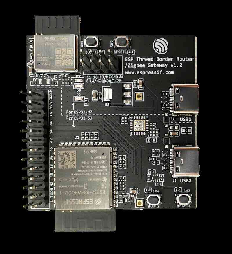
  1. get the ESP Thread Border Router, potentially with Ethernet shield (optional, I think it’s worth it though)
  2. go to Releases · espressif/esp-thread-br · GitHub and get the latest release. It’s a little bit involved, you do have to compile stuff and so on, but you don’t really need to understand any of it and just follow the linked documentation from the release page. In short you need to build esp.idf and use the thread border router example from a second repo (it’s called examples, but it’s actually what you wanna use). This docs also helped a bit. The USB-C port to use is the one labeled “USB2” (but seems that both work?). It takes quite some time to clone and build everything (and is a bit confusing that you build stuff for esp32 h2 first, but do not flash it, it gets flashed afterwards when you are flashing the main part: ESP32-S3.) You don’t need to really setup thread details via that menuconfig, that can be done later (if I understand correctly). This guide shows that the last command is idf.py -p flash monitor which is nonsense, you need a parameter afterwards. On my mac, the last command was idf.py -p /dev/cu.usbmodem2101 flash monitor (your path might be different of course). However, you can drop that monitor in case you just want to flash the thing, this can be later brought in via idf.py -p /dev/cu.usbmodem2101 monitor. It will spit out logs and gets you into a console, chances are high that you don’t need this for anything. To quit this console press CTRL+], a bit of a gotcha. Note that to changing wifi name and creds you need idf.py -p /dev/cu.usbmodem2101 erase-flash flash monitor. The official guide also described how to e.g. manually use the console to connect to the Wifi or how to setup up a thread device to connect to it (2.1.5. Build and Run the Thread CLI Device section). If you are like me - you want a dumb thread border router that just connects and starts automatically, ignore the rest of the guide there once you flash the firmware (that means that you want that autostart etc.).
  3. Once you connect it to the network, you should be able to get it up and running. I really just followed the guide above - the ethernet version, connected it to my router via ethernet cable and then I was able to access it under the mDNS http://esp-ot-br.local/index.html (note the index.html, it’s mandatory) or also via local IP like 192.168.0.33/index.html.
  4. In that web gui there is a settings that you can “Form” a new network on http://esp-ot-br.local/index.html#Form. You should change the default settings. I generated new PAN ID and Extended ID using echo "PANID: 0x$(printf '%04X' $((1 + RANDOM % 65534)))" && echo "Extended PANID: $(od -An -N8 -tx1 /dev/urandom | tr -d ' ' | tr '[:lower:]' '[:upper:]')", changed the channel from default 15 to 25 so it can sit next to existing zigbee on 26 with as little overlap with wifi, used a different Passphrase/Commissioner Credential (just any string) and also generated random 32 long hex string (there are online generators) to use as a Network Key.
  5. That should be enough, once you click on Form Network, it should create it. Note that if you refresh the page, it will be gone, the web gui is abyssmal, i.e. it doesn’t work for me, showing “unknown” name etc… So don’t get surprised it doesn’t “save”.
  6. Then in HA enable Open Thread Border Router and in the configuration put in the IP address of your newly created device from the above, like http://192.168.0.33. Then add a Thread integration. Your border router should show up there as “Other Networks”. Click on three dots and let it be “Make a preferred network”. That should be it, this should now be the main network. AFAIK you don’t need an android or apple device or companion app, this should be enough. Do not try to use the border router to add it into a HA created thread network - that would wipe the settings from the Open Router.

If you sucedeed, you should see something like this:

3 Likes

Hey! What is your way of running HA?
I am running from a container (podman compose), and also own an ESP Thread Border Router. My Thread client device (running ESPHome) gets an IPv6 address, which I can ping from my machine, as well as the border router itself, so I presume the firmware side of configuration is correct. I am also able to add the OTBR and Thread integrations, and I can see my Thread network with all the details, much like your screenshot. The weird part, HA says I have no border router on the thread network, despite the fact that my BR says on it’s interface it’s the leader of the thread network. HA shows a reset button, all it does is changes the thread network hosted by the border router, but still shows up as “no border router”. Do you have any idea what my issue could be?
Also FYI, clicking on the blue “status” in thread network status section of the page, after a few seconds it fetches the details and you’re able to see the values.

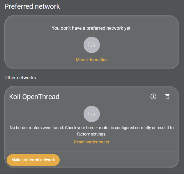
Hmm. Not sure. Have you added Open Thread Border Router integration as well? :thinking: So you don’t see the router in the Thread view at all? Post a screenshot of this screen:
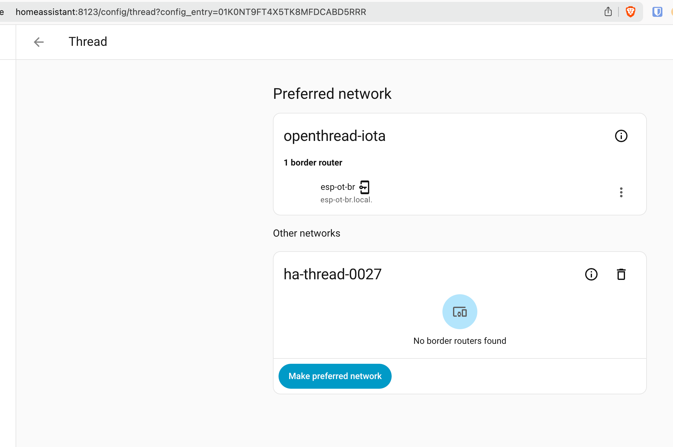
Also FYI, clicking on the blue “status” in thread network status section of the page, after a few seconds it fetches the details and you’re able to see the values.

Yeah, I wrote some findings here btw. Failing to connect ESP-H2 via Thread - #4 by kotrfa

Thanks for getting back! Yes, I have added the OpenThread Border Router integration, pointed at the mDNS local domain address of the router. It shows up only this far


I stil have the logs running from the border router connected to my PC, thread-rf-bridge is my would-be client thread device on a separate H2, the IP address resolves just fine.

I feel like I’m out of my depth here… :sweat_smile:

HA Thread settings shows a list of networks detected by means of the mdns broadcasts to _mechcop._udp.local service. It seems these broadcasts aren’t reaching your machine, either because it’s on a different WiFi subnet/vlan, or because something on your network/host is blocking the multicast dns packets (e.g. router or firewall). Are you using multiple vlans? Can you see the meshcop advertisements in the HA zeroconf browser (settings → system → network), or from another device running a zerocconf browser app?

Can you ping this IP from any host on your network, or only from border routers? If the former, the border routers are doing their job and the only problem seems to be the HA detection part. If you aren’t planning to commission Matter-over-Thread (or HomeKit-over-Thread) devices with HA, then you really don’t need it to see your TBRs, but it does point to a potential problem on your network if it can’t.

This is weird to me. It says there is no border router, but it gives you a button to reset the (nonexistent) border router?? This settings page is a UX disaster. Maybe the OTBR integration (which is separate from the Thread integration) is connected to an OTBR REST API but still no mdns broadcasts are coming through? There should be a better way of presenting this to the user.

If it would be mDNS, couldn’t it help to use IP address directly in OTBR?

I second that the UI is pretty bad… There have been already a lot of suggestions how to make it better on HA github, so I think it’s at least tracked, and I myself have added a couple of them.

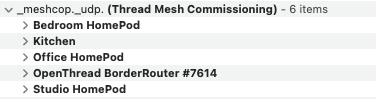
mDNS not being used for name resolution in this case, it’s being used for service discovery. Thread Border Routers “announce” themselves using multicast zeroconf packets, so if you have an app that can view them such as “Discovery” for MacOS, you can see your TBR announcements on the local LAN:

meshcop-udp

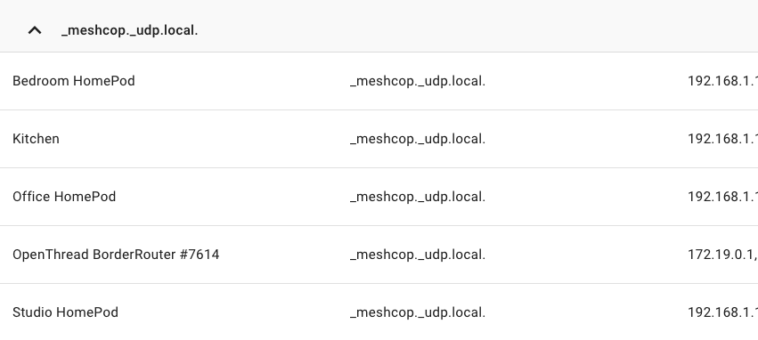
If they are being received by HA they should show up in its built-in zeroconf browser, which is what makes them appear on the Thread settings page:

This is just service discovery, which isn’t technically needed for the router to do its job (routing). For that, it sends out IPv6 router advertisements (RAs) so that hosts on the LAN know the “nexthop address” to the Thread subnet IP range. It is possible that your RAs are working and you can ping Thread devices even if mDNS service discovery is broken (however you need the mDNS part working if you want to use Matter, as it is a prerequisite).

For example, on a Linux machine I can see all the routes to my Thread subnet, one from each TBR:

peter@sarah:~$ ip -6 route
::1 dev lo proto kernel metric 256 pref medium
fdaf:c551:c359::/64 proto ra metric 1024 expires 1668sec pref medium
	nexthop via fe80::c05:63f8:ea9d:cfff dev enp1s0 weight 1 
	nexthop via fe80::fb:e6f6:1481:6aff dev enp1s0 weight 1 
	nexthop via fe80::cc6:db46:9e3e:74ff dev enp1s0 weight 1 
	nexthop via fe80::1066:ac0e:ce97:fdff dev enp1s0 weight 1 
	nexthop via fe80::18b8:6b02:a291:e0ff dev enp1s0 weight 1 

On my MacOS machine I can only see the chosen route:

peter@whistler ~ % netstat -rn -f inet6 | grep fdaf:c551:c359
fdaf:c551:c359::/64                     fe80::18b8:6b02:a291:e0ff%en1           UGc                   en1       

I can confirm using the Discovery app (screenshot above) by expanding my TBR details that this fe80 address belongs to one of my border routers. If I traceroute to a Thread device I should expect it to use this TBR as the next hop:

peter@whistler ~ % traceroute6 5E99DF85BBD8433C.local
traceroute6: Warning: 5e99df85bbd8433c.local has multiple addresses; using fdaf:c551:c359:0:a805:5d3a:784f:2f1
traceroute6 to 5e99df85bbd8433c.local (fdaf:c551:c359:0:a805:5d3a:784f:2f1) from fdc4:4aab:e77f:e44c:1c53:e1b9:c62a:83dd, 64 hops max, 28 byte packets
 1  fdc4:4aab:e77f:e44c:81b:8955:4a71:e3ff  11.543 ms  7.511 ms  5.909 ms
 2  fdaf:c551:c359:0:a805:5d3a:784f:2f1  27.794 ms  34.724 ms  33.154 ms

Here it’s showing me the ULA instead of the LLA but again I can check my Discovery app output to see that it’s just another address on the same TBR.

1 Like

Hey, thanks for the reply! Yep, resetting the border router I don’t have :smiley: Your theory seems plausible to me.
I have multiple SSIDs and VLANs, running on Unifi, but I have configured the border router to be on the same VLAN.
My HA instance shows no zeroconf discovery at all. I installed BonjourBrowser on my phone, which sees my TrueNAS and my BSB-LAN but not the thread BR. So could already be 2 potential issues.
As for IPs, I was able to ping from both my HA host OS and my separate PC, to the border router and the thread client device I had. I don’t have any matter or homekit devices as for now, all i have is a test ESPHome board.

Wow, thanks for the description, this is very helpful even for me now, I am sure I will find this handy (and already see how this seems to be much better than zigbee introspectibility)!

I was able to confirm that indeed meshcop udp advertisements are sent by the BR, as I’m able to see them from my machine. I am now pretty sure my issue is with running rootless podman, without capabilities such as CAP_NET_RAW. I’m not sure this looks solvable in rootless mode for now. I am going to have to try switch to running as root probably

I was able to figure it out. I have switched to rootful Home Assistant but still nothing would come up. Turns out my nftables config was a bit too strict and I didn’t outright allow mDNS UDP traffic. I am now able to see my Border Router as expected

For the life of me I can’t get it to flash, it is one different error after another. I tried getting the AI robots to help, but I just end up in a loop. Has anyone found any videos or easy instructions? I am not sure if it is windows related or what

For me it was really that point 1 in my OP. Happy to help if you share the problem/error stack. Start over and share where you get stuck.

Thanks @kotrfa. I have been playing with it over the last few days. Very frustrating… Initially for the first part I was trying to build through WSL VM in Windows, then windows ESP-IDF cmd & powershell prompt, then espressif-ide application. When I changed the various options listed in the guides, it would just fail the final build.

Yesterday I switched to doing it in one of my linux VM’s instead, that built fine and I was excited that it may work. Then when I went to flash, it flashed but got into a boot loop and never gets out… I can’t really paste the log because it is all jumbled into one line…

ESP-ROM:esp32s3-20210327 Build:Mar 27 2021 rst:0x3 (RTC_SW_SYS_RST),boot:0x8 (SPI_FAST_FLASH_BOOT) Saved PC:0x403758bf --- 0x403758bf: esp_restart_noos_dig at /home/spaldo/Public/esp-idf/components/esp_system/port/esp_system_chip.c:57 SPIWP:0xee mode:DIO, clock div:1 load:0x3fce3818,len:0x1750 load:0x403c9700,len:0x4 load:0x403c9704,len:0xbe4 load:0x403cc700,len:0x2d18 entry 0x403c9908 I (27) boot: ESP-IDF v5.1.2 2nd stage bootloader I (27) boot: compile time Jan 21 2026 19:49:07 I (27) boot: Multicore bootloader I (30) boot: chip revision: v0.2 I (34) boot.esp32s3: Boot SPI Speed : 80MHz I (39) boot.esp32s3: SPI Mode : DIO I (44) boot.esp32s3: SPI Flash Size : 4MB I (48) boot: Enabling RNG early entropy source... I (54) boot: Partition Table: I (57) boot: ## Label Usage Type ST Offset Length I (65) boot: 0 nvs WiFi data 01 02 00009000 00006000 I (72) boot: 1 otadata OTA data 01 00 0000f000 00002000 I (80) boot: 2 phy_init RF data 01 01 00011000 00001000 I (87) boot: 3 ota_0 OTA app 00 10 00020000 00190000 I (94) boot: 4 ota_1 OTA app 00 11 001b0000 00190000 I (102) boot: 5 web_storage Unknown data 01 82 00340000 00019000 I (109) boot: 6 rcp_fw Unknown data 01 82 00359000 000a0000 I (117) boot: End of partition table I (121) esp_image: segment 0: paddr=00020020 vaddr=3c0f0020 size=4b464h (308324) map I (185) esp_image: segment 1: paddr=0006b48c vaddr=3fc96600 size=04a7ch ( 19068) load I (190) esp_image: segment 2: paddr=0006ff10 vaddr=40374000 size=00108h ( 264) load I (191) esp_image: segment 3: paddr=00070020 vaddr=42000020 size=ee82ch (976940) map I (375) esp_image: segment 4: paddr=0015e854 vaddr=40374108 size=124d0h ( 74960) load I (399) boot: Loaded app from partition at offset 0x20000 I (400) boot: Disabling RNG early entropy source... I (400) cpu_start: Multicore app I (404) cpu_start: Pro cpu up. I (407) cpu_start: Starting app cpu, entry point is 0x403754b0 --- 0x403754b0: call_start_cpu1 at /home/spaldo/Public/esp-idf/components/esp_system/port/cpu_start.c:157 I (0) cpu_start: App cpu up. I (423) cpu_start: Pro cpu start user code I (423) cpu_start: cpu freq: 160000000 Hz I (423) cpu_start: Application information: I (425) cpu_start: Project name: esp_ot_br I (427) cpu_start: App version: v1.0 I (429) cpu_start: Compile time: Jan 21 2026 19:48:54 I (433) cpu_start: ELF file SHA256: f1a4fe4991901cfe... I (434) cpu_start: ESP-IDF: v5.1.2 I (434) cpu_start: Min chip rev: v0.0 I (434) cpu_start: Max chip rev: v0.99 I (435) cpu_start: Chip rev: v0.2 I (437) heap_init: Initializing. RAM available for dynamic allocation: I (442) heap_init: At 3FCA9688 len 00040088 (256 KiB): DRAM I (442) heap_init: At 3FCE9710 len 00005724 (21 KiB): STACK/DRAM I (442) heap_init: At 3FCF0000 len 00008000 (32 KiB): DRAM I (442) heap_init: At 600FE010 len 00001FD8 (7 KiB): RTCRAM I (444) spi_flash: detected chip: generic I (444) spi_flash: flash io: dio W (444) spi_flash: Detected size(8192k) larger than the size in the binary image header(4096k). Using the size in the binary image header. I (448) sleep: Configure to isolate all GPIO pins in sleep state I (450) sleep: Enable automatic switching of GPIO sleep configuration I (450) app_start: Starting scheduler on CPU0 I (451) app_start: Starting scheduler on CPU1 I (461) main_task: Calling app_main() I (521) mdns_mem: mDNS task will be created from internal RAM I (531) RCP_UPDATE: RCP: using update sequence 1 I (531) OPENTHREAD: spinel UART interface initialization completed I (531) main_task: Returned from app_main() W(2541) OPENTHREAD:[W] Platform------: Wait for response timeout I (2541) esp_ot_br: Internal RCP Version: openthread-esp32/482a8fb2d7-af5938e38; esp32h2; 2026-01-21 09:47:18 UTC I (2541) esp_ot_br: Running RCP Version: I (2541) gpio: GPIO[7]| InputEn: 0| OutputEn: 0| OpenDrain: 0| Pullup: 1| Pulldown: 0| Intr:0 I (2541) gpio: GPIO[8]| InputEn: 0| OutputEn: 0| OpenDrain: 0| Pullup: 1| Pulldown: 0| Intr:0 E (2901) RCP_UPDATE: esp_rcp_update(247): Failed to connect to RCP ESP-ROM:esp32s3-20210327 Build:Mar 27 2021 rst:0x3 (RTC_SW_SYS_RST),boot:0x8 (SPI_FAST_FLASH_BOOT) Saved PC:0x403758bf --- 0x403758bf: esp_restart_noos_dig at /home/spaldo/Public/esp-idf/components/esp_system/port/esp_system_chip.c:57 SPIWP:0xee mode:DIO, clock div:1 load:0x3fce3818,len:0x1750 load:0x403c9700,len:0x4 load:0x403c9704,len:0xbe4 load:0x403cc700,len:0x2d18 entry 0x403c9908 I (27) boot: ESP-IDF v5.1.2 2nd stage bootloader I (27) boot: compile time Jan 21 2026 19:49:07 I (27) boot: Multicore bootloader I (30) boot: chip revision: v0.2 I (34) boot.esp32s3: Boot SPI Speed : 80MHz I (39) boot.esp32s3: SPI Mode : DIO I (43) boot.esp32s3: SPI Flash Size : 4MB I (48) boot: Enabling RNG early entropy source... I (54) boot: Partition Table: I (57) boot: ## Label Usage Type ST Offset Length I (64) boot: 0 nvs WiFi data 01 02 00009000 00006000 I (72) boot: 1 otadata OTA data 01 00 0000f000 00002000 I (79) boot: 2 phy_init RF data 01 01 00011000 00001000 I (87) boot: 3 ota_0 OTA app 00 10 00020000 00190000 I (94) boot: 4 ota_1 OTA app 00 11 001b0000 00190000 I (102) boot: 5 web_storage Unknown data 01 82 00340000 00019000 I (109) boot: 6 rcp_fw Unknown data 01 82 00359000 000a0000 I (117) boot: End of partition table I (121) esp_image: segment 0: paddr=00020020 vaddr=3c0f0020 size=4b464h (308324) map I (185) esp_image: segment 1: paddr=0006b48c vaddr=3fc96600 size=04a7ch ( 19068) load I (189) esp_image: segment 2: paddr=0006ff10 vaddr=40374000 size=00108h ( 264) load I (191) esp_image: segment 3: paddr=00070020 vaddr=42000020 size=ee82ch (976940) map I (374) esp_image: segment 4: paddr=0015e854 vaddr=40374108 size=124d0h ( 74960) load I (399) boot: Loaded app from partition at offset 0x20000 I (400) boot: Disabling RNG early entropy source... I (400) cpu_start: Multicore app I (404) cpu_start: Pro cpu up. I (407) cpu_start: Starting app cpu, entry point is 0x403754b0 --- 0x403754b0: call_start_cpu1 at /home/spaldo/Public/esp-idf/components/esp_system/port/cpu_start.c:157 I (0) cpu_start: App cpu up. I (423) cpu_start: Pro cpu start user code I (423) cpu_start: cpu freq: 160000000 Hz I (423) cpu_start: Application information: I (425) cpu_start: Project name: esp_ot_br I (427) cpu_start: App version: v1.0 I (429) cpu_start: Compile time: Jan 21 2026 19:48:54 I (433) cpu_start: ELF file SHA256: f1a4fe4991901cfe... I (433) cpu_start: ESP-IDF: v5.1.2 I (433) cpu_start: Min chip rev: v0.0 I (433) cpu_start: Max chip rev: v0.99 I (435) cpu_start: Chip rev: v0.2 I (437) heap_init: Initializing. RAM available for dynamic allocation: I (441) heap_init: At 3FCA9688 len 00040088 (256 KiB): DRAM I (441) heap_init: At 3FCE9710 len 00005724 (21 KiB): STACK/DRAM I (442) heap_init: At 3FCF0000 len 00008000 (32 KiB): DRAM I (442) heap_init: At 600FE010 len 00001FD8 (7 KiB): RTCRAM I (443) spi_flash: detected chip: generic I (443) spi_flash: flash io: dio W (443) spi_flash: Detected size(8192k) larger than the size in the binary image header(4096k). Using the size in the binary image header. I (448) sleep: Configure to isolate all GPIO pins in sleep state I (449) sleep: Enable automatic switching of GPIO sleep configuration I (450) app_start: Starting scheduler on CPU0 I (450) app_start: Starting scheduler on CPU1 I (460) main_task: Calling app_main() I (520) mdns_mem: mDNS task will be created from internal RAM I (530) RCP_UPDATE: RCP: using update sequence 0 I (530) OPENTHREAD: spinel UART interface initialization completed I (530) main_task: Returned from app_main() W(2540) OPENTHREAD:[W] Platform------: Wait for response timeout I (2560) esp_ot_br: RCP firmware not found in storage, will reboot to try next image ESP-ROM:esp32s3-20210327 Build5

huh, seems your h2 is not doing anything. You do have this board, am I right?


AFAIK the firmware should be pushed to H2 during the boot, but it never makes it to the H2 because the UART communication between S3→H2 isn’t working for whatever reason.

Yep, that is my board. Did you make any of the changes that are mentioned in different places for these options:

  • LWIP_IPV6_NUM_ADDRESSES
  • SPI interface
  • RF External Coexistence
  • Port mapping changes
  • or editing any .h files, etc

Good news is that I got it running, bad news is I am not sure exactly what I did. I guess if anything, instead of using multiple guides I followed this one a little closer and I also used these versions:

git clone -b v5.4.2 --recursive https://github.com/espressif/esp-idf.git
git clone -b v1.2 https://github.com/espressif/esp-thread-br.git

Cool. I did not do any changes to those setting you mentioned. And the web interface i think was also enabled by default, but it is part of the compile config do you might enable it there, but you would have to reflash

For those that may search and find they have the same problem as I did, this is what I think I ended up doing below. I used Linux VM with the ESP Thread BR board attached to USB2, changed the versions to a more stable option,

Set up Repositories & load ENV

git clone -b v5.4.2 --recursive https://github.com/espressif/esp-idf.git
cd esp-idf
./install.sh
. ./export.sh
cd ..
git clone -b v1.2 https://github.com/espressif/esp-thread-br.git

Configure the Thread and the Wi-Fi network

cd esp-thread-br/examples/basic_thread_border_router
idf.py menuconfig
  • Enable automatic start mode in Thread Border Router: ESP Thread Border Router Example > Enable the automatic start mode in Thread Border Router.
  • Wi-Fi SSID and PSK: Example Connection Configuration > connect using Wi-Fi interface
  • I also enabled the web gui here, much easier to manage

Escape out and press save when you exit the menu. Pressing ‘S’ in the menu didn’t seem to save for me.

Build the OpenThread RCP side (H2 side of board) - don’t flash

cd ${IDF_PATH}/examples/openthread/ot_rcp
idf.py set-target esp32h2
idf.py build

Build & flash the Border Router side (S3 side of board) - this will flash the H2 side on boot

cd esp-thread-br/examples/basic_thread_border_router
idf.py set-target esp32s3
idf.py build
idf.py -p /dev/ttyUSB0 flash monitor

Because I already had a Google Nest thread network in HA and wanted to “join” them together with the new ESP interface, I didn’t create a new one and joined/merged it all with these commands while still in the console:

dataset set active <NEST_TLV>
dataset commit active
ifconfig up
thread start

To get the TLV from Nest, I pressed the ‘i’ button in the HA thread page and copied it from that. There may be other ways to get it if you are also doing this and don’t have it in HA…

1 Like

I was able to closely follow the instructions and successfully flash my OTBR (with Ethernet addon). However, I can’t get it to work when not connected to a PC. If I power it via a USB port of my PC or laptop - it works just fine. If I power it with a USB charger - it does nothing.

I have tried 3 different known good chargers and a handful of cables, including ones that worked with the PC/laptop. I also tried powering it from my laptop using a power-only USB cable, and it did not work. This leads me to believe that the device is expecting a working USB data link in order to start working.

I don’t know anything about ESP32 development, does anybody know of a way to fix this?