An interesting looking device - a wall switch with a touch screen. Advertised as both mqtt and home assistant compatible, and there is a tasmota template too.

Yesterday I received the dimmer @home
It’s a nice looking product, with some limitations.
The dimmer leaks power, so the lightbulb stays on all the time.
This ca be fixed to use a bypass.
The second issu is on the Home Screen.
When I swipe a bit above the slider to increase the  then the whole screen moves.
It doesn’t happen when the slider is precisely is pressed.
1 Like

Has anyone tried to flash this with HA Switch Plate (HAsp) https://github.com/fvanroie/hasp-lvgl
Would really love to know if this would work.
I need a way for switches in my house to control:
Light Dimming
Fans
Curtains
Heating
No the lanbon is not a nextion device.
The link I sent was the Open Hardware HASP, which supports non-nextion devices.
It supports ESP32, which the Lanbon is.
This project is a re-implementation of the popular HASwitchPlate sketch created by aderusha. The original HASwitchPlate project uses a Wemos D1 mini and requires a Nextion/TJC HMI display. This rewrite removes the Nextion/TJC requirement by using the Littlev Graphics Library on the MCU to drive a cheap commodity display. This version also adds ESP32 and STM32F4 support to take advantage of the additional hardware capabilities.
My apologies, I didn’t know of that implementation of HASP. Interesting…
I guess it will depend if the display in the lanbon is supported in hasp-lvgl.
See HA SwitchPlate - DIY LCD Touchscreen wall switch replacement which suggests it does work.
Hi there, openHASP indeed runs on that switch! blakadder recently published a review of some alternate firmwares for the Lanbon L8, including hasp-lvgl.
We have now published a .bin for it to test, but not all features are supported yet. HA integration is still being worked on, etc… Check out the hasp-docs for more info on the project or feel free to join our Discord channel.
2 Likes
Can setup with Tasmota:
1 Like
There is a review here https://blakadder.com/lanbon-L8/ and reviews of alternate firmware here https://blakadder.com/lanbon-L8-custom-firmware/
1 Like
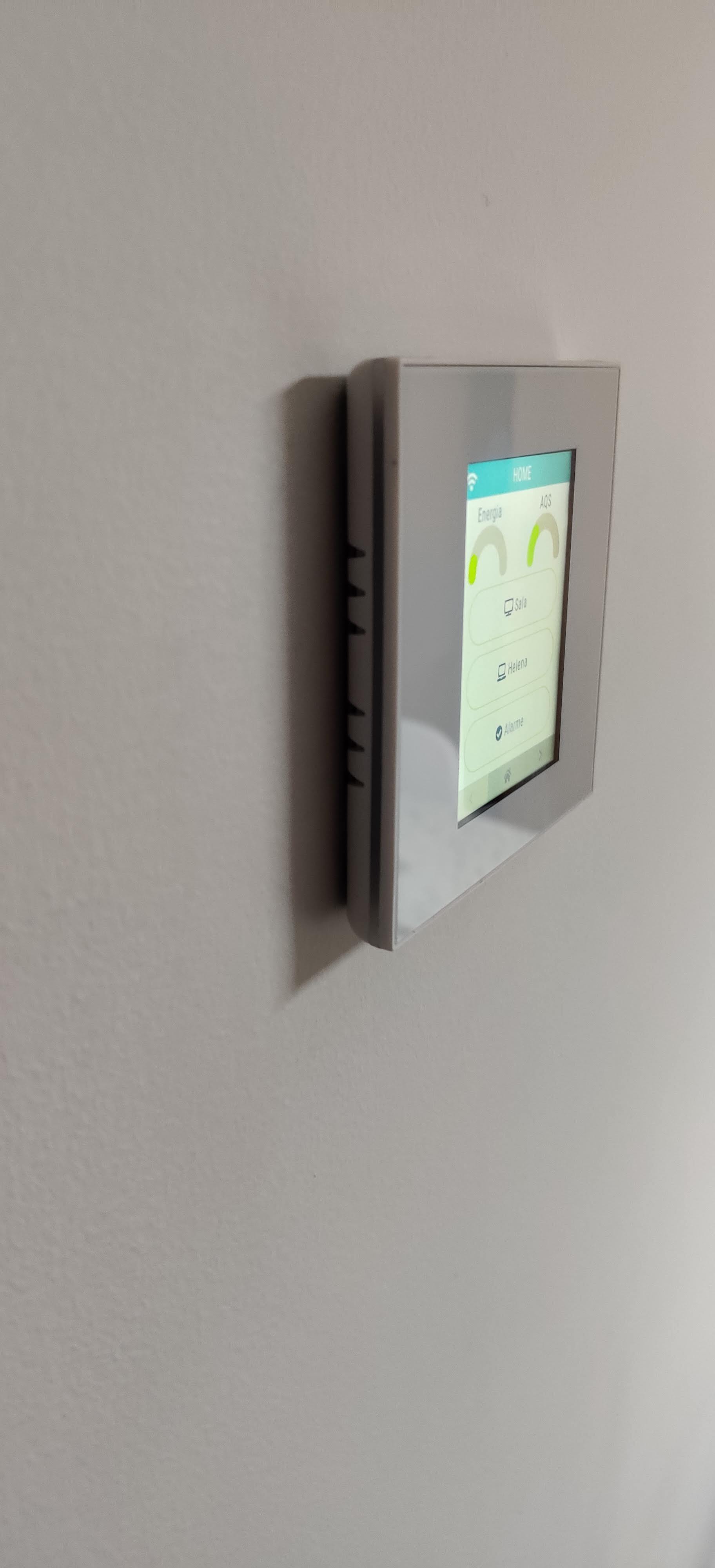
Bought one, super happy! well build, looks nice on the wall 
Actually ended up using https://fvanroie.github.io/hasp-docs/# instead of Tasmota.
I also created https://github.com/dgomes/hasp-lvgl to easily integrate with HA

3 Likes
Thanks for posting an actual picture of the switch on the wall. Gives a nice impression of how it looks like.
I have a couple of questions on the build quality, if you don’t mind. It’s probably due to the perspective of the photo, but it looks like the screen is not perfectly aligned with the frame, like if there is a slight rotation. Do you observe that in reality too ?
It also looks like the screen itself is slightly recessed behind the transparent front plate ? I assume this is what creates the black borders around it ?
And finally, what is your impression of the screen quality itself, in terms of contrast, sharpness, etc. Does it look high end, or more like a flip phone screen from 15 years ago ? 
Thanks !
2 Likes
Well it was not a well though picture 
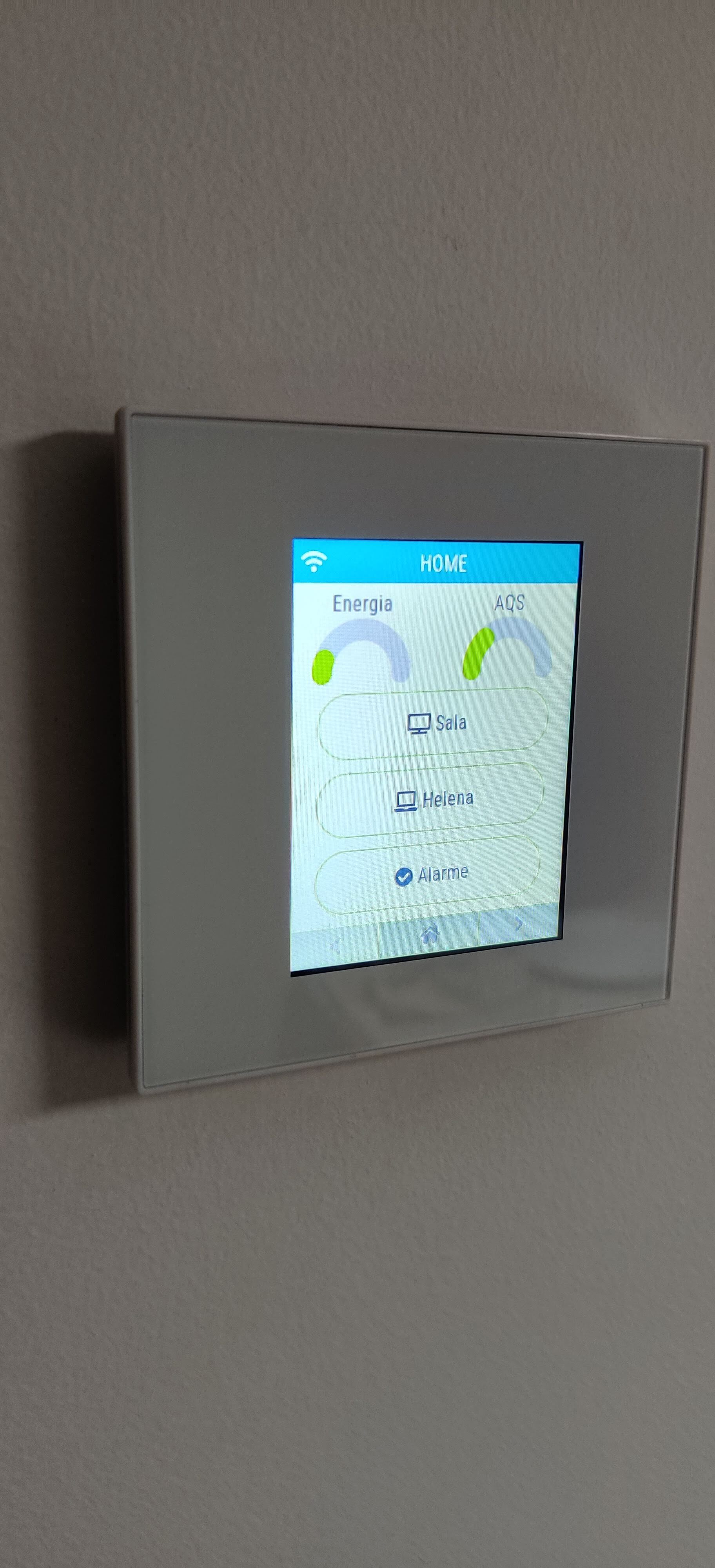
The frame and LCD are aligned, plastic is of high quality and you have a glass in front of it all (that’s why you have the black around, its just shadow).
it’s a basic LCD, you are not going to have pictures in it … 320x240 pixels…
ultimately, for the price of the thing, you get what you pay for, and I’m not complaining here
Extra pictures:
4 Likes
Great, thanks for the additional info !
Can anybody with the L8-HD dimmer version check what dimming MCU they are using?
We are trying to gather some info on dimmer device and protocol used to talk to the module.
@fvanroie, i just ordered one. Where do I look for this info?
Hi juan,
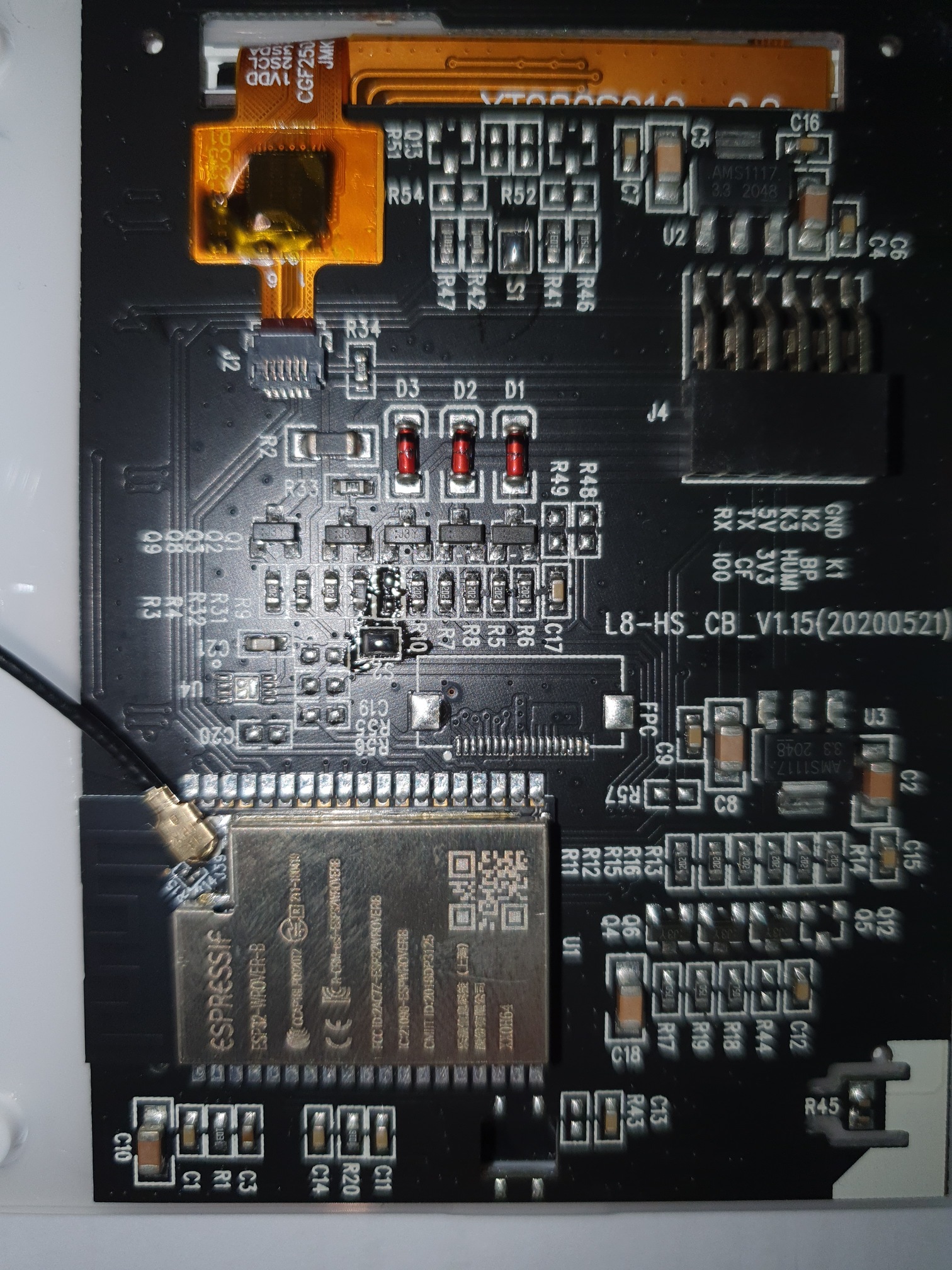
We’ve compared the PCBs and these seem to be exactly the same as the Lanbon-L8-HS switch. So the dimming occurs in the base and is controlled via the small pin-header.
We have reason to believe the communication between the ESP32 and dimming MCU is serial based but I don’t know what pins or baudrate is used. That’s the next step we’re trying to find out, either via a scope on the pins or serial UART when it’s detached from the base…
The goal is to add support for the dimmer in our custom firmware.
Where do I look for this info?
It might be difficult to access the PCB in the base without tearing-down the device. I don’t have one myself, so can’t really tell exactly where to look. Any information, pictures, etc will be helpful though.

I think @fvanroie wanted to see the other PCB that is attached to that one.